Section 2: Interpretation of Soil Data
Anchor: #i1035788Overview
A critical step in foundation design is determining strata and reasonable strengths to be assigned to each stratum. Divide the subsurface materials into strata based on material description and test values. Review all tests within each stratum to evaluate the variability of the data. If a single, unusually high strength test is present among a group of distinctly lower test values, disregard the anomalous test value. An average strength may be assigned for an entire layer as long as the test values are reasonably similar.
Avoid defining very thick strata with widely variable test values. Subdivide thick strata with test values varying from soft near the top to distinctly harder toward the bottom into two or more strata with compatible values. Failure to subdivide may result in an unconservative average strength being applied to foundations that terminate in the upper zone of that stratum.
An acceptable option to producing average unit values for strata is to calculate using a more rigorous, test-by-test basis.
Anchor: #i1031284Disregard Depth
Disregard surface soil in the design of drilled shafts and piling foundations. The disregarded depth is the amount of surface soil that is not included in the design of the foundation due to potential erosion from scour, future excavation, seasonal soil moisture variation (shrinkage and swelling), lateral migration of waterways, and other factors. Disregard a minimum amount of 5 ft. over non-water crossings and 10 ft. over stream crossings. For abutments, disregard the portion of foundation passing through embankment fills.
It is important to note that for projects where the existing ground line is at an elevation considerably higher than the proposed grade line (roadway is to be depressed) soil softening, swelling or heave must be accounted for in design of embankment slopes, roadways, retaining walls and foundation elements. Soils in these conditions respond to the removal of overburden (unloading). This response could have a dramatic impact on the design approach taken.
Additional information regarding disregarded depth is available online.
Anchor: #CIHIFIIBTexas Cone Penetration Test
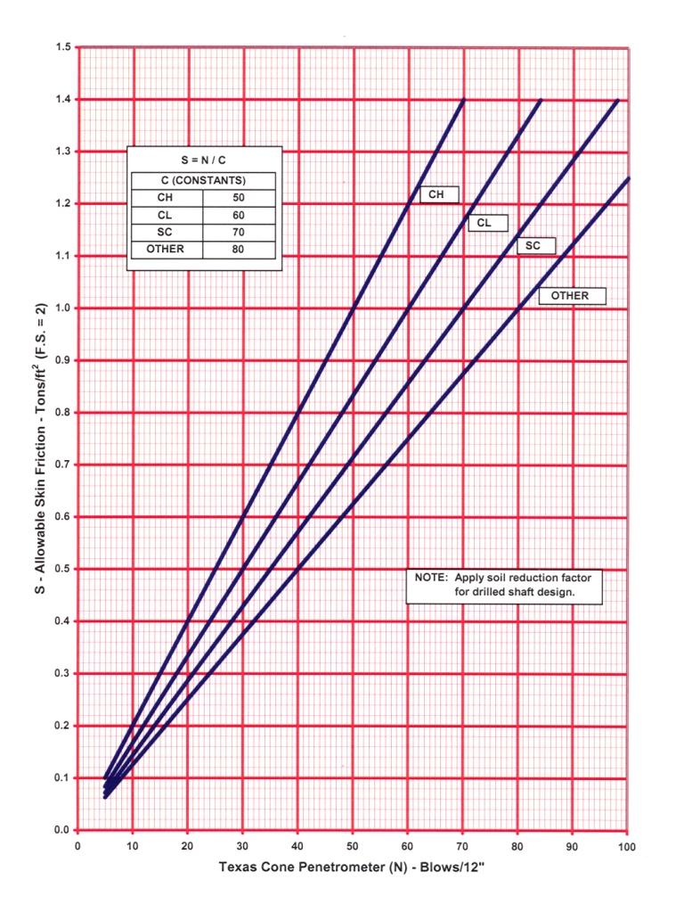
Use the following charts to determine skin friction and point-bearing capacity based on Texas Cone Penetration data for drilled shaft and piling designs. Use Figure 5-1 to determine allowable skin friction for soil softer than 100 blows/12 in. Select the curve based on the description of the soil type.
Use the CH curve in clay soil identified as high-plasticity, or fat clay. Use the CL curve in clay soil identified as low-plasticity, or lean clay. In clay soil, use the CL curve if no specific identification is provided regarding plasticity. Use the SC curve for soil described as either sandy clay or clayey sand. Use the OTHER curve for soils described as silt, sand, gravel or any layers not fitting into one of the previous designations.
For drilled shaft designs, multiply the allowable design stress by a reduction factor of 0.7. The reduction factor is used to account for disturbance of the soil during drilling. Application of the reduction factor to the design of driven piling is not necessary.
Figure 5-1. Allowable Skin Friction (TCP Values Softer than 100 Blows/12 in.)
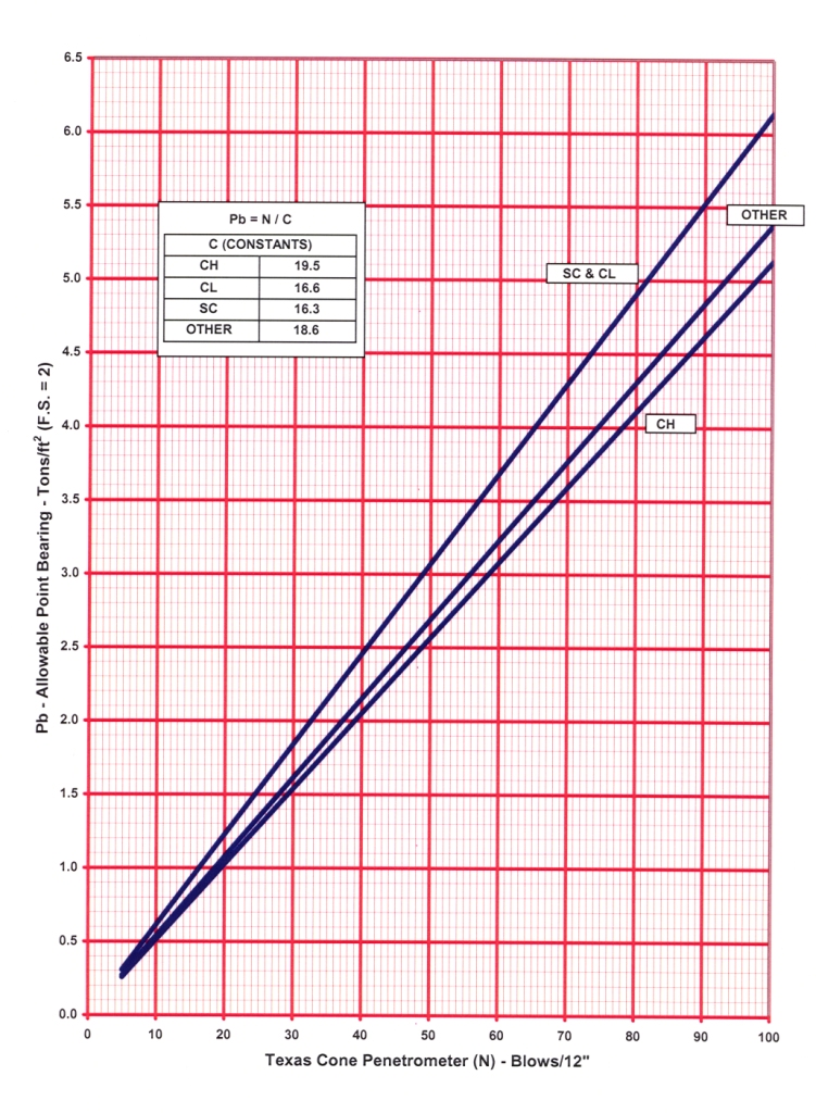
Use Figure 5-2 to determine allowable point bearing for soil softer than 100 blows/12 in. Select the curve based on the description of the soil type, using the criteria noted for the previous chart.
Figure 5-2. Allowable Point Bearing (TCP Values Softer than 100 Blows/12 in.)
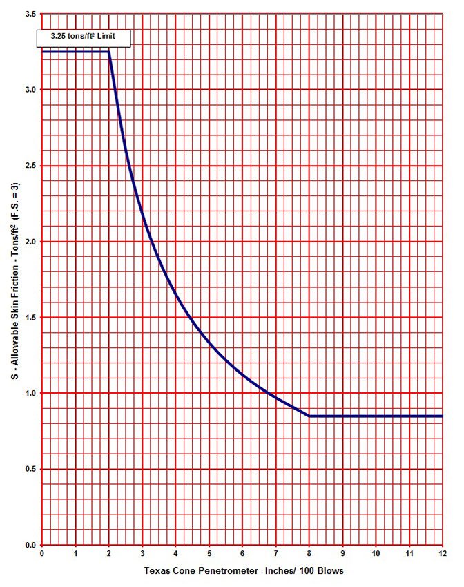
Use Figure 5-3 to determine allowable skin friction for soil or rock strata harder than 100 blows/12 in. The upper limit of 3.25 tons/ft2 applies for all Texas Cone Penetration values less than 2 in/100 blows. Do not apply skin friction reduction factor to values obtained from this figure because this figure is derived only for use in drilled shaft design. Piling typically cannot be driven into soil of this strength, so this figure is not generally used for piling design.
Figure 5-3. Allowable Skin Friction (TCP Values Harder than 100 Blows/12 in.)
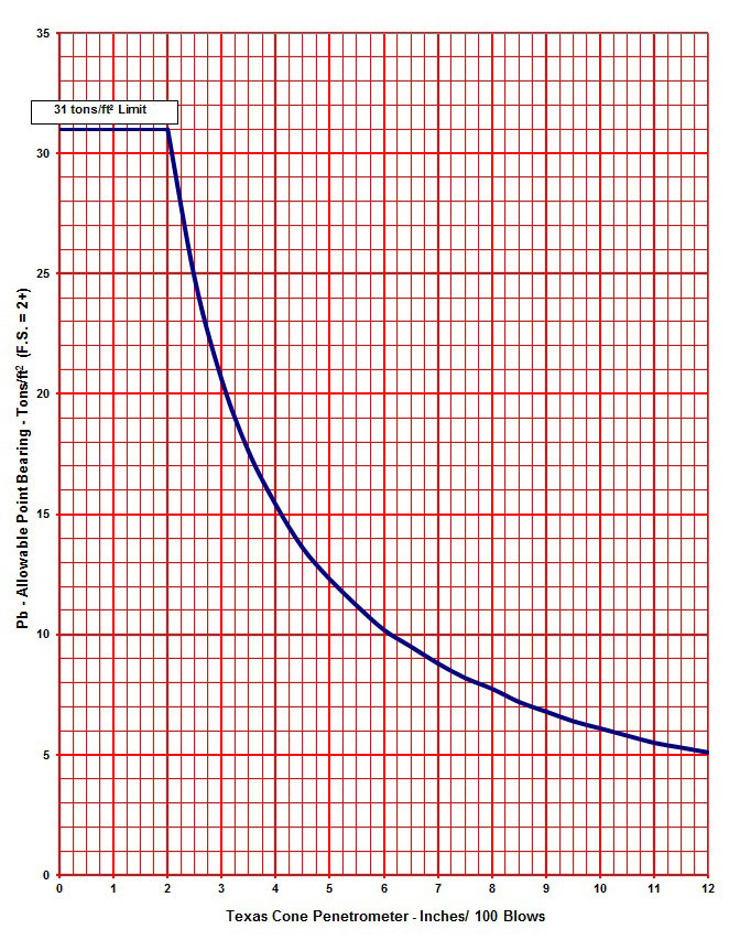
Use Figure 5-4 to determine allowable point bearing for soil or rock strata harder than 100 blows/12 in. The upper limit of 31 tons/ft2 applies for all Texas Cone Penetration values less than 2 in/100 blows.
Figure 5-4. Allowable Point Bearing (TCP Values Harder than 100 Blows/12 in.)
Anchor: #i1036082Laboratory Test
If additional strength data is available from triaxial or direct shear testing, use this data with TCP data in the design of foundations. Determine the ultimate shear strength for each stratum using Coulomb’s formula (Shear Strength = τ = c’ + σy’ (tan φ’). Determine allowable skin friction by applying a factor of safety of at least 2.0 to the ultimate shear strength. For drilled shaft design, reduce the allowable skin friction value by an additional reduction factor of 0.7 to account for soil disturbance. Determine allowable point bearing by multiplying the ultimate shear strength by a bearing capacity factor of 9 and then dividing by a factor of safety of at least 2.0.


