Section 3: Asphalt Distributor
Anchor: #i1007564General
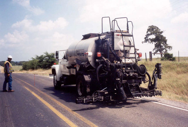
The asphalt distributor is the most complex piece of equipment used in seal coat construction work because it has many components, and all must be operating properly. An asphalt distributor is a truck-mounted, insulated tank, with numerous special purpose attachments. A typical asphalt distributor is shown in Figure 7‑3.
Figure 7-3. Typical Asphalt Distributor.
The major components are:
- Anchor: #CTWPGCDV
- Asphalt tank Anchor: #WVBWGDFF
- Heating system Anchor: #JCNMJNKW
- Circulating and pumping system Anchor: #MNKRDNNR
- Filter screens Anchor: #AROBBBTS
- Spray bar Anchor: #CGQXSPAD
- Hand sprayer Anchor: #WRPTMIFE
- Controls and gauges.
The inspectors should record the serial number and model of the asphalt distributor and enter this information in the project folder.
Anchor: #i1007629Asphalt Binder Tank
The asphalt distributor tanks vary in size. Those used for most seal coat work hold from 1000 to 2000 gallons of asphalt binder. Some tanks may be larger or smaller, but this range is adequate for most jobs. The tank is insulated to prevent the asphalt from cooling too quickly. Asphalt cement temperatures for seal coat work are commonly well over 300°F. If the tanks were not well insulated, the asphalt would cool quickly near the skin of the tank and could harden to unworkable levels.
The distributor must have a current calibration certificate in accordance with Test Method Tex-922-K, Part I. This means that the distributor has been checked to determine the accuracy of the measuring stick (strap stick) and the capacity of the tank. The calibration certificate is considered valid as long as it is current and there is no evidence or reason to suspect that any major modifications have been made to the distributor tank.
The tank unit should be visually inspected inside before it is filled. It should be clean to prevent contamination or mixing of different types of asphalt. Extreme caution should be used to avoid chemical or physical reactions that can occur when different asphalt binders are inadvertently used in the same tank.
The heater unit should be checked for proper starting and operation. Each burner should operate independently to allow either one to be used alone or simultaneously. The burner flames must be adjustable to regulate the amount of heat being directed into the flues. The fuel lines and burners should be free of fuel leaks.
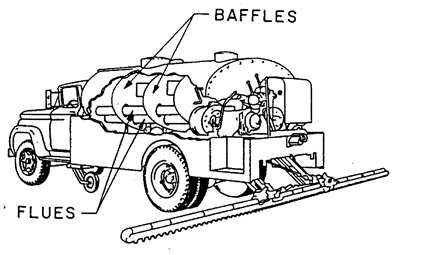
Baffle Plates and Flues. The inside of the tank contains two or three baffle plates to stabilize the load while in motion. This is especially critical where a constant spray pressure is necessary. The tank has either one or two flues or heat ducts running lengthwise of the tank. These flues allow heat to be conducted into the center of the tank. In spite of the insulation in the tank, some heat loss is inevitable. By use of a burner system in combination with recirculation within the tank, the asphalt can be heated uniformly. Figure 7‑4 shows the baffles and flues running through the asphalt tank.
Figure 7-4. Illustration of Baffles and Flues Inside Distributor Tank.
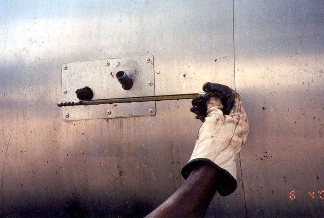
Thermometer. The tank should be equipped with a thermometer. The thermometer should have a range from below 100°F to at least 400°F. Many models have a mercury thermometer mounted in a well in the side of the tank. It should have a chain to prevent it from being dropped and a screw-on cap to keep the well covered. Some models of distributors use a dial-type thermometer mounted outside the tank. These use a thermocouple that is mounted inside the tank. Both types of thermometers are acceptable and should be checked for accuracy. Infrared thermometers can be used to verify asphalt temperature. Another verification technique is to obtain a sample of the asphalt from the distributor and check with a separate thermometer. Figure 7‑5 shows the tank thermometer being removed for taking a temperature reading.
Figure 7-5. Thermometer Removed from Distributor Tank.
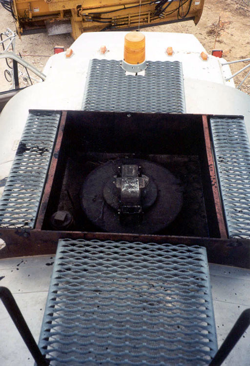
Manhole. At the top of the tank is an opening commonly called a manhole. It has a heavy, hinged lid with a fastener. The manhole is used in filling the tank and permits visual inspection of the tank and its contents. The manhole is also opened to measure the amount of asphalt in the tank using a calibrated strap stick. The measuring process is called “strapping the tank” and will be described in detail in Seal Coat/Surface Treatment Application Process. Figure 7‑6 shows the manhole cover from the top of the tank.
Vent. All asphalt distributor tanks are equipped with a vent. The location of the vent will vary according to the manufacturer. Care should be taken to ensure that the distributor is always parked where there is adequate crosswind to prevent an accumulation of fumes (from the vent) to come in contact with the burner flame.
Figure 7-6. Manhole Cover on Top of Distributor Tank.
Anchor: #i1007712Distributor Heating System
Asphalt temperature is a critical factor in the success of a seal coat/surface treatment. To maintain a constant temperature, a proper heating system is necessary.
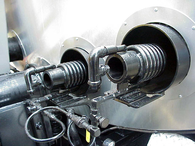
Burners. Depending on the make and size of the distributor, either one or two propane or diesel fired burners are used. The burners are mounted on the platform at the rear of the tank and are positioned so the flame is directed into the flues that pass through the tank. Figure 7‑7 shows a typical configuration.
Figure 7-7. Burner Configuration at Rear of Tank.
Heating. The need for heating will depend on the following:
- Anchor: #IWXHFEBM
- Type of asphalt binder being used Anchor: #IROYFQBX
- Ambient temperature Anchor: #SGDCKRPQ
- Length of time the binder is in the distributor before being sprayed on roadway Anchor: #YIDINAUN
- Whether the distributor is filled directly from heated storage tanks or has been hauled some distance in an insulated transporter.
Most emulsions used for seal coats are applied at 120°F to 160°F. When using asphalt cement, application temperatures may range from 275°F to 375°F. Application temperatures for cutback asphalts may range from 125°F to 275°F. Cutbacks should be shot 25°F to 50°F below their respective flash point. For each binder type, refer to Item 300, Asphalts, Oils, and Emulsions, for correct heating and application temperatures.
Anchor: #i1007776Distributor Circulation and Pumping System
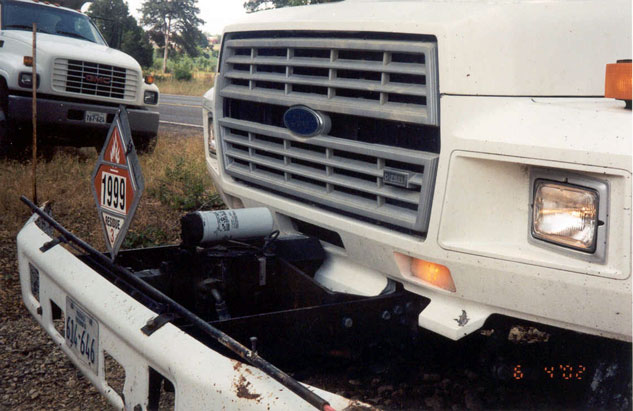
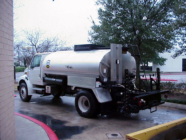
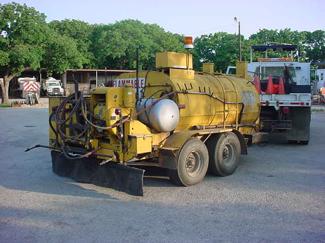
All asphalt distributors must have a power-driven pump to spray asphalt under pressure onto the roadway. The pumps also serve to provide a circulation system. There are two systems commonly used to supply pressure to the spray circulation system. One system has a separate engine mounted at the rear of the tank. This engine supplies power to the pump only. The other system uses power from the truck engine to operate the pump. This is called a hydrostatic distributor system as seen in Figure 7‑8. A truck-mounted asphalt distributor is shown in Figure 7‑9 and a trailer-mounted distributor is shown in Figure 7‑10.
Figure 7-8. Hydrostatic Distributor Located at Front of Truck.
Figure 7-9. Truck-Mounted Asphalt Distributor.
Figure 7-10. Trailer-Mounted Asphalt Distributor.
Function. In addition to providing the power to spray asphalt binder on the road, the pump provides power to perform the following functions:
- Anchor: #FQLHBONI
- Circulate the asphalt throughout the tank. This is necessary to prevent asphalt from burning if it remained next to the flues for an extended period. Also, it will prevent asphalt from remaining near the skin of the tank long enough to cool and harden. Anchor: #MYCYELLL
- Circulate asphalt through the spray bar and bring unused asphalt back into the tank. This will prevent asphalt from remaining in the spray bar long enough to cool, harden, and clog the spray nozzles. Anchor: #YFVORHON
- Pump unused asphalt out of the distributor. Anchor: #ADAWMVOH
- Pump from one storage tank to another. It may be used as an auxiliary pump to transfer asphalt from one tank to another. Anchor: #CJKQIQJR
- Fill the distributor tank. If a storage tank, heater unit, or transporter unit is not equipped with a pump, the distributor spray pump may be used to fill the distributor tank.
Filter Screens
Most distributors have filter screens in the main piping between the tank and the spray bar. The purpose of these wire-mesh filters is to prevent particles of burned asphalt or impurities from entering the spray bar and clogging the spray nozzles.
These screens should be removed and washed with diesel fuel, or particles should be burned off with a torch. This will prevent a blockage of the flow of asphalt, allowing it to flow under full pressure to the nozzles. On a large project, the filters should be cleaned periodically.
Anchor: #i1007863Distributor Spray Bar
The spray bar and spray nozzles regulate the amount of asphalt sprayed on the roadway and regulate the spray pattern. Figure 7‑11 shows a typical distributor spray bar.
Figure 7-11. Typical Distributor Spray Bar.
The spray bar on most distributors used on seal coat projects is 12 feet wide – the width of a typical traffic lane. Different bar widths are available. Ten to 14-foot widths are recommended.
The bar is composed of a series of spray nozzles evenly spaced (every 4 inches) along the bar. It contains a return line for continuous circulation of asphalt through the bar. Some models are equipped with shut-off valves on each nozzle to allow closing a few spray nozzles for spraying irregular areas. Figure 7‑12 shows the nozzles on a typical spray bar.
Figure 7-12. Nozzle on Typical Spray Bar.
Hinged Bar. Most spray bars are hinged at each end to allow the end to be folded up when spraying is not in progress. The distributor should never be driven in traffic with the ends extended, because they extend beyond the sides of the truck. Some have chains attached at the ends of the bar and to the truck chassis. The chains help to support the ends of the bar when they are in the spray position. Chains may also serve as a safety hitch to hold the ends securely in the upright position. Figure 7‑13 shows the spray bar ends folded up.
Figure 7-13. Hinged Spray Bar with Ends Folded Up.
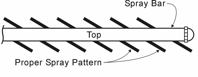
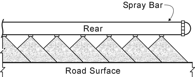
Spray Nozzles. Nozzles are manufactured with different size openings to permit different application rates of asphalt. Nozzles are designed to spray a fan-shaped pattern, rather than a circular spray. Viewed from the top they would look as shown in Figure 7‑14. Viewed from behind the distributor, they would appear as shown in Figure 7‑15. Some distributors are equipped with a second spray bar, sometimes called a wheelpath bar. This second spray bar is used to spray a different application rate in the wheelpath and is controlled with a separate computer.
Figure 7-14. View of Distributor Bar as Seen from Top of Distributor.
Figure 7-15. View of Distributor Bar as Seen from Rear of Distributor.
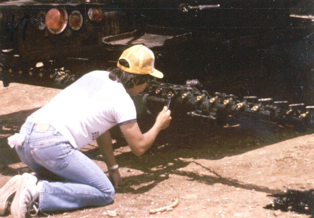
Inspecting the Spray Bar. To inspect the spray bar, it should be raised and, if possible, rotated outward so the nozzles can be inspected as shown in Figure 7‑16. The nozzles are critical to obtain uniform asphalt coverage. They must be in good condition and properly oriented to obtain consistent asphalt coverage across the width of the lane being sealed. Nozzles are typically made of brass and can easily be gouged or otherwise damaged, which will affect spray pattern.
Figure 7-16. Distributor Spray Bar Rotated Outward.
The following is a list of several items on the spray bar that must be inspected.
- Anchor: #ROKOEFNI
- Spray Bar Ends. The ends of the bar should be checked to see that they can be raised and lowered. There should be some method of securing the ends in the raised position. Most models are equipped with a chain device to secure the ends when raised. Anchor: #FWPKHHQK
- Bar Position. The bar should be straight when the ends are lowered. This should be checked in all directions. Spray patterns will be distorted if the bar is not straight. Anchor: #EDJXLCAM
- Hoses, Joints and Pipes. There should be no leaks in any of the hoses, joints, and pipes. If asphalt leaks onto the pavement when the distributor is not spraying, a puddle of asphalt will form. This type of spill is difficult to clean up and will usually result in too much asphalt at that location which will bleed through the cover aggregate. Anchor: #DXUYOVRD
- Spray Bar Width. The spray bar must be checked to ensure it is the correct width. Ensure that the proper amount of extensions and nozzles have been installed to cover the required width. Anchor: #HGDDQDJR
- Spray Bar Height. The height of the spray bar should be checked. The distributor must be parked on a flat, level surface, with the bar in the lowered position. The height should be measured from the bottom of the nozzles to the pavement surface. Measurements should be taken at various points across the width of the spray bar to ensure that the height is constant. Set the height according to the manufacturer’s recommendations. The bar height should be measured first with the tank empty and checked again after the tank is full. If there is more than about 1 inch difference corrective action should be taken. This will prevent a change in the overlap of the fan pattern between the beginning and end of a shot. Anchor: #PEDAMCIP
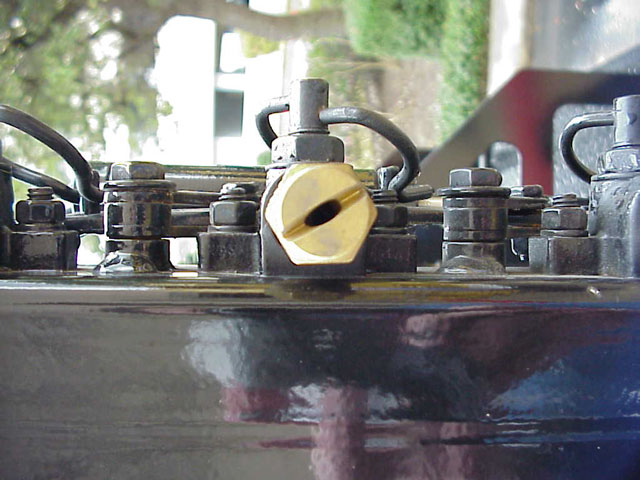
- Spray Nozzles. A nozzle is mounted every 4 inches along the width of the spray bar. The correct number of nozzles should be in place for the width being sealed. If a variable spray rate is to be used, the nozzles should be checked to see that they are the proper size and in the correct location. If there are more nozzles than needed, the operator should close off the extra nozzles. To achieve a straight, sharp edge of asphalt coverage, use a deflector nozzle at the ends of the spray bar. Do not allow the end nozzle to be turned perpendicular to the spray bar axis in an attempt to get a sharp edge, because it will cause too much asphalt at the edge and it robs the next nozzle of the overlap normally provided by the end nozzle.
Nozzle Angle. The nozzles must be set to the proper angle according to manufacturer’s specifications. The angle is usually between 15° to 30° as shown in Figure 7‑17, depending on the manufacturer. All nozzles must be set at the same angle to avoid distortion of the spray pattern. Every distributor should be equipped with a tool used to accurately set the proper angle.
Figure 7-17. Nozzles on Spray Bar Set at Manufacturer’s Recommended Angle.
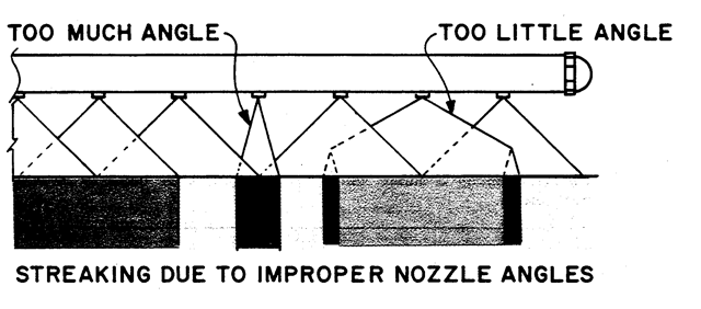
The proper spray pattern depends directly on the exactness of the nozzle angles. If not set correctly, the fan pattern can be distorted as shown in Figure 7‑18.
Figure 7-18. Effect of Incorrect Nozzle Angle.
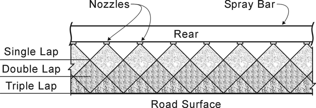
Fan Width. In addition to the nozzle angle, the height of the spray bar is critical to obtaining a correct spray pattern. The height of the bar above the surface of the roadway determines how wide the fan spreads. Triple lap coverage as shown in Figure 7‑19 is desirable and is achieved at a spray bar height of 12 inches.
Figure 7-19. Various Asphalt Spray Patterns.
Standard truck springs will compress under a heavy load, and flex back to an arch when the load is removed. If an asphalt distributor had standard springs, the spray bar would be one height when the tank is full. As the asphalt is sprayed and the tank empties, the spray bar would rise with the decreased weight on the springs. Consequently, the beginning of the shot would have triple lap coverage, but the lap would increase as the spray bar height increases. This would cause streaking.
To avoid this inconsistency, most distributors are equipped to either prevent the springs from compressing under a load or to prevent them from arching back with a near-empty tank. Many are stabilized with compressed air. The important point is that the spray bar should remain at a constant height whether the tank is full or empty.
To check the fan width, the operator should back onto a flat area and place one or two layers of brown paper under the spray bar. Have the operator turn the spray on momentarily. Make certain he turns it off as quickly as possible. This will not give an exact representation of the fan widths, but it will quickly reveal any problems with the spray pattern. If this is not conclusive, the operator may spray a short test strip (20 to 30 feet). This will usually reveal any nozzle problems.
Nozzle Output. The amount of asphalt being sprayed out of each nozzle will vary. Nozzle output should be tested in accordance with TxDOT Test Method Tex 922-K, Part III (bucket test) to ensure each nozzle is spraying within the correct tolerance.
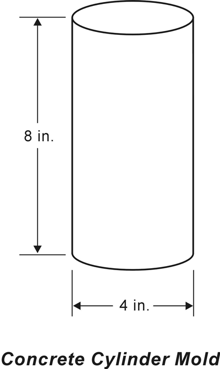
Buckets for the bucket test must be shaped so they will fit under the nozzles side-by-side. A 4-inch diameter by 8-inch height concrete cylinder mold as shown in Figure 7‑20 is commonly used for the bucket test.
Figure 7-20. Concrete Cylinder Mold Typically Used for Spray Bar Calibration.
If asphalt is used for the test, it should be heated to the temperature at which it will be applied. Water may also be used for this test. Before the test begins, the spray bar should be turned on for a short period of time to make certain none of the nozzles are clogged. The distributor should be moved off the test area to blow out the nozzles.
If all nozzles are working, the test can proceed. If any nozzles are clogged, they should be removed and cleaned or taken out of service.
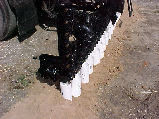
A container should be placed under each nozzle to catch all the flow from that nozzle as shown in Figure 7‑21. Set the pump pressure or speed to match the application rate for the seal coat work. When the containers are all in position, turn the sprayer on briefly to fill the containers to about 3/4 full.
Figure 7-21. Calibration of Asphalt Distributor Spray Bar.
Item 316, Surface Treatments, requires that there be no more than a 10 percent variation in the weight of the contents between each bucket. If water is used for this test, all water must be removed from the distributor tank after calibrating the spray bar. Adding hot asphalt will cause water in the tank to be converted to steam resulting in an explosion, which may result in serious injury. At the least the asphalt tank is likely to overflow via the manhole, possibly endangering those nearby.
Transverse Variation. Some seal coat work may require the application of more asphalt binder outside the wheel paths to prevent aggregate shelling. The rate variation can be achieved by using different nozzle sizes outside the wheel path versus in the wheel path.
Anchor: #i1008111Hand Sprayer
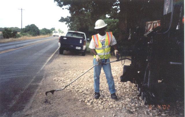
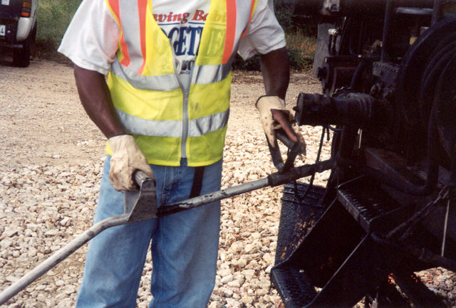
All distributors should be equipped with a hand sprayer for use in narrow, irregular-shaped areas that are inaccessible to the spray bar. Figure 7‑22 shows a typical hand sprayer. The handle shown on the right side of Figure 7‑23 also serves as the shut-off valve control. To turn the spray on, the operator turns the handle 90°.
Figure 7-22. Typical Hand Sprayer on Asphalt Distributor.
Figure 7-23. Handle-Control Valve.
Anchor: #i1008143Distributor Controls and Gauges
The asphalt distributor must deliver a uniform and precise amount of asphalt onto the roadway. Equally as important is the need for consistency throughout the length of the asphalt shot. Many gauges and controls are necessary to achieve this consistency.
Thermometer. As mentioned earlier, a thermometer is used for monitoring asphalt temperature. Most are located in a well in the side of the tank. Some models have a dial thermometer mounted on the outside of the tank, with a thermocouple inside the tank. This type is more convenient to use and easier to read than the mercury thermometer, which must be removed from the well, but it is subject to malfunctions.
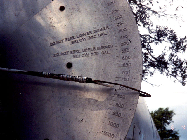
Volume Gauge. Most tanks are equipped with a volume gauge as shown in Figure 7‑24. These should be used only as a convenience to the operator to know when the tank is getting close to empty. They should never be used as the basis for payment.
Figure 7-24. Volume Gauge on Distributor Tank.
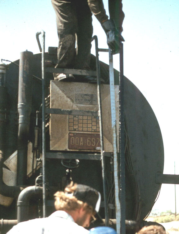
Strap Stick. The manufacturer supplies a measuring stick (strap stick) with the distributor. Some distributors have the gallon levels on the stick itself. Others have a metal scale riveted on the side of the frame as seen in Figure 7‑25. The stick or scale must be in accordance with Test Method Tex-922-K, Part I. A discussion of how the distributor is “strapped” is provided in Chapter 8.
Figure 7-25. Strap Stick Used to Measure Quantity of Asphalt in Distributor Tank.
Pump Pressure or Rate. All asphalt distributors have a power-driven pump to spray asphalt under pressure onto the roadway. The pumps also serve to provide a circulation system. Some distributors measure the pump pressure in pounds per square inch (psi) in the lines. This type of distributor is equipped with a conversion chart supplied by the manufacturer. The chart converts the amount of psi into gallons per minute (gpm) dispensed at the spray bar. Another type of distributor has the pump rate measured in gallons per minute increments. The gauge is a very important device, because the pressure under which asphalt is being sprayed will greatly influence the quality of the job. If the pressure is too low, the asphalt will streak and the pattern will be uneven. If the pressure is too high, the asphalt may atomize and the pattern may be distorted. The ill effects of this are magnified by high wind.
The pump should be operated at the highest pressure possible without atomizing the asphalt. The way to determine the ideal pressure or pump rate is through field tests. Once the ideal pressure is determined from the test, the pump should be operated at that rate or pressure.
Most distributors are computerized so that the desired binder application rate is set by the distributor operator who then must operate the vehicle at a specific engine RPM.
Digital-Measuring Instrument (DMI). Specifications require that a vehicle be furnished with a calibrated digital-measuring instrument, accurate to plus or minus 6 feet per mile. The inspector should verify that no modifications have been made that might affect the accuracy of the measuring instrument since calibration.
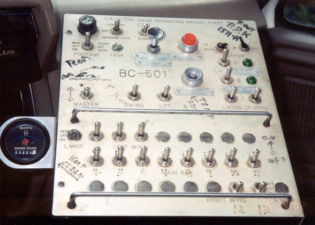
Valve Control. Another important control is the valve control which turns the spray on and off. A distributor operator must be able to turn all spray nozzles on and off simultaneously and instantaneously. This is a simple task in a computerized distributor and can be accomplished from inside the cab with a switch on the control panel as shown Figure 7‑26.
At the beginning and end of a shot, the distributor passes over paper, which masks the pavement to form a straight, sharp line. The distributor must pass over the masking paper on both ends at spraying speed. The operator must be able to turn all nozzles on in the split second that the distributor passes over the masking paper.
Figure 7-26. Computerized Asphalt Distributor Controls.
A computerized distributor may be operated by one person, but a manually operated distributor requires two people. On manually operated distributors, the driver lines up the machine and keeps it on line at the correct speed, while the spray operator works the valve control, and, on some models, sets the pump motor speed and monitors pump pressure. These two people must work as a team.

