Section 4: Aggregate Spreader
Anchor: #i1008241General
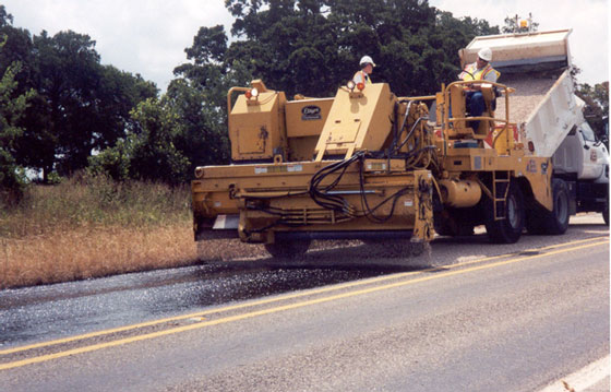
The aggregate spreader, sometimes called the “spreader box” is used to distribute aggregate evenly over the film of asphalt sprayed by the asphalt distributor. The specifications require aggregate spreaders to be self-propelled and have a continuous feed feature. The type most commonly seen on a seal coat project is shown in Figure 7‑27.
Figure 7-27. Aggregate Spreader or Spreader Box.
The spreader receives aggregate from a haul truck that dumps the aggregate into a receiving hopper at the rear of the spreader. A conveyor system transports the aggregate to another bin at the front of the vehicle. Gravity spreads the aggregate evenly across adjustable gates, which allow precise amounts of aggregate to pass through.
The major components of the aggregate spreader are as follows:
- Anchor: #PHWGYHRD
- Truck hitch Anchor: #JHDLTNWA
- Receiving hopper Anchor: #PHFHUIWH
- Belt conveyors Anchor: #NWWKNSCX
- Spreading hopper Anchor: #NTGACYIJ
- Discharge gates Anchor: #EATLONFX
- Discharge roller.
The spreader must distribute cover aggregate at a uniform rate over the entire width and length of the area being sealed. Not only must it be uniformly spread, it must also be the correct quantity of aggregate. For a clear understanding of how this is done, each component of the spreader will be described further in this section.
Part of the visual inspection of the aggregate spreader should be directed at the overall condition of the power train, primarily detecting evidence of leaks in the engine and transmissions.
The manufacturer’s name, spreader model number, and serial number should be recorded.
Anchor: #i1008316Truck Hitch
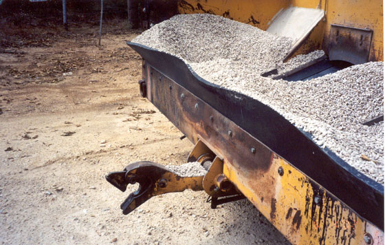
To be operated properly, the haul truck should back up to the spreader; a coupling on the spreader should engage on the rear of the truck; the coupling should lock securely together; and the spreader box should pull the truck (in neutral gear position) behind it. The truck should not push the spreader box. This is very important, because the amount of aggregate covering the asphalt depends partially on the traveling speed of the spreader. Thus, to maintain a constant speed and ensure a uniform aggregate application rate, the spreader must regulate its own speed.
The spreader coupling must be able to lock securely with the truck hitch, and the spreader box operator must be able to release the hitch easily and quickly. Figure 7‑28 is a photo of a typical spreader box truck hitch arrangement.
The truck hitch should be visually checked for anything broken or bent. Ensure the locking mechanism is working properly by having a truck hook up to the spreader box. Have the operator manipulate the release to be sure it will disengage the truck effectively.
Figure 7-28. Aggregate Spreader Truck Hitch.
Anchor: #i1008346Receiving Hopper
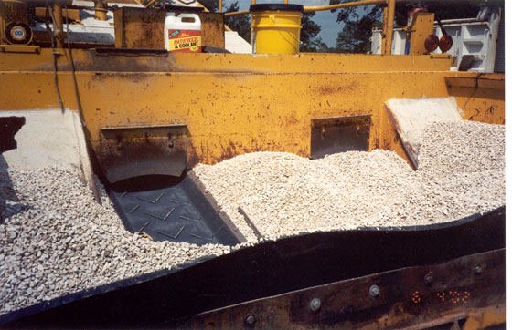
After the truck has engaged the hitch on the spreader, the truck bed is raised and aggregate is dumped into the receiving hopper. The receiving hopper is seen in Figure 7‑29. Its only function is to receive the aggregate from the truck. At the bottom of the receiving hopper, there are openings through which the belt conveyors must pass in a continuous loop. A rubber shield prevents aggregate from piling up on the belt, being carried ahead of the receiving hopper and being spilled onto the ground. This shield should not be torn or missing so that it can function properly.
Figure 7-29. Receiving Hopper of Aggregate Spreader.
The receiving hopper should be visually checked for overall condition. There should be no holes or large gaps that would allow aggregate to fall through to the road surface. The conveyor belt system should have rubber, neoprene, or fabric cowling (or flaps) around it to prevent aggregate loss. There should also be a flap on top of the receiving hopper to ensure a tight fit against haul trucks as the aggregate is being dumped into the receiving hopper.
Anchor: #i1008371Belt Conveyors
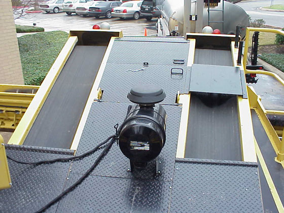
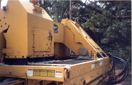
There are two belt conveyors, which transport the aggregate. These can be seen on each side of the photo in Figure 7‑30. These belts must be in good condition and not frayed enough to allow aggregate to spill over the sides onto the roadway.
The operator should start the conveyors and demonstrate the speed control. The speed should be variable to ensure that the supply of aggregate reaching the front hopper can be increased or decreased as needed.
There should not be an excessive amount of slack in the belts since this will cause sagging and loss of aggregate off the sides. If there is too much slack, the belts must be tightened.
Figure 7-30. Belt Conveyors on Aggregate Spreader.
Anchor: #i1008401Discharge Hopper
The discharge hopper receives the aggregate from the belt conveyors and distributes it laterally in the hopper. The aggregate falls over two angular devices at the top of the discharge hopper, as seen in Figure 7‑31. Also in this photo is a scalping device. This can consist of either a series of bars or a coarse mesh to separate any large rocks, dirt clods, or weeds from the aggregate.
The hopper should be checked to ensure that it is clean and does not contain any aggregate particles from a previous project. The scalping grate should be checked to ensure that it covers the entire top of the hopper. This grate performs the very important function of keeping large clay balls and other foreign matter out of the fresh asphalt binder. Also, there should be no holes or cracks in the hopper, where aggregate can fall through and cause a ridge or row of excess aggregate.
The exterior of the discharge hopper should be checked for damage. Occasionally, a spreader will be driven over a large rock or other object damaging the lower front corners. Damage of this sort may be critical, because the roller bearings are held in a casing in this section of the hopper. Damage can cause the roller to wobble resulting in an uneven flow of aggregate.
Figure 7-31. Discharge Hopper of Aggregate Spreader.
Anchor: #i1008431Discharge Gates
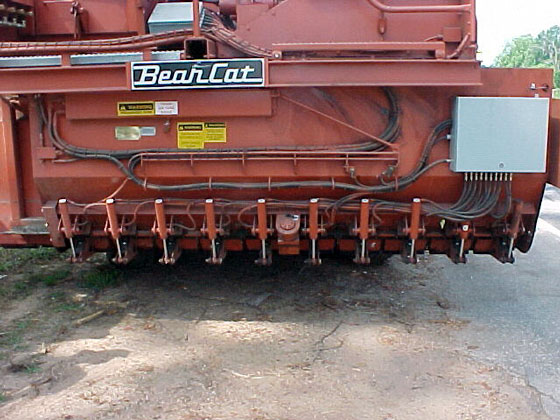
On the bottom of the discharge hopper are a series of discharge gates as shown in Figure 7‑32 that can be opened by operator control to discharge the aggregate. Each gate can also be opened or closed individually by a switch located at the top and in the front of the discharge hopper.
Check to see that they are correctly adjusted to close the gates fully. You will not be able to judge whether the adjustment is correct when the gates are open, until the spreader is actually dispensing aggregate.
Figure 7-32. Discharge Gates on Aggregate Spreader.
Anchor: #i1008456Discharge Roller
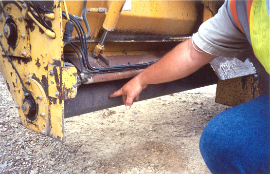
Some aggregate spreaders have a roller at the bottom of the discharge gates which spins to assure an even flow of aggregate onto the asphalt. This roller (Figure 7‑33) ensures that an even amount of aggregate is spread laterally across the pavement. The roller must be straight, not warped, for the aggregate to be distributed evenly.
The discharge roller should be visually examined to ensure there is no mud or other debris caked on its surface. A string line should be stretched from end to end of the roller to be certain it is not warped. To check the end bearings of the roller for excessive wear, the spreader should then be turned on and observed for wobble in the roller or noise coming from the bearings as they turn.
Figure 7-33. Discharge Roller on Aggregate Spreader.
Anchor: #i1008481Wheels and Tires
With the spreader in motion, the wheels should be observed for any indication of wheel wobble or excessive toe-in or toe-out. Any of these conditions will tend to cause the tires to scuff the aggregate. The spreader box is the first vehicle to drive over the freshly placed aggregate, and when the spreader’s tires pass over the aggregate, the aggregate particles will still be in unarranged positions. Any scuffing by the spreader’s tires may shove the aggregate sideways rather than straight downward. Scuffing will appear as a dark, ragged-looking strip causing asphalt to be picked up on the tires of the pneumatic rollers.
The tires should be checked to detect any gouges that might adversely affect the aggregate arrangement. Gouges that may weaken the sidewall could lead to a tire blowout. This type of faulty tire should be changed before the project starts.
Anchor: #i1008496Brakes and Clutch
The operator should stop and start the spreader a few times so the operation of the clutch and brakes can be checked.
Anchor: #i1008506Tailgate Aggregate Spreader
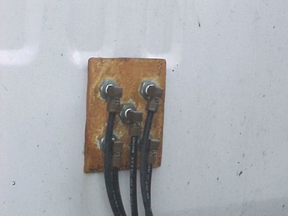
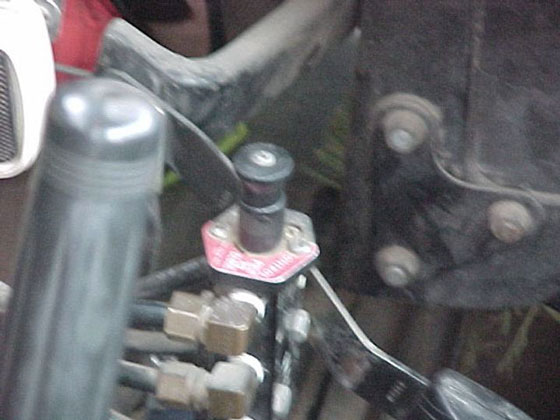
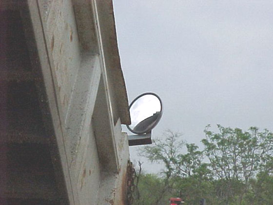
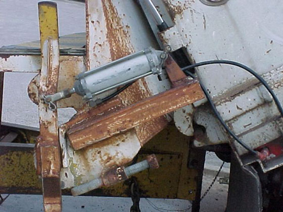
The tailgate of a haul truck is sometimes used as an aggregate spreader by state maintenance forces in spot sealing. Some TxDOT districts have installed air-operated tailgate spreaders. Figures 7‑34 through 7-37 show how modifications can be made to the typical truck so that an employee is no longer needed to ride on the tailgate spreader. This will reduce the number of employees needed in the crew and improve safety in the operation.
Figure 7-34. Air Line Connections on Back of Truck Cab
Figure 7-35. Control Valve in Truck Cab.
Figure 7-36. Mirror to View Rock in Truck and Rock Flow
Figure 7-37. Air Cylinder to Open/Close Spreader
