Section 6: Displaced Left Turn Intersection (DLT)
Anchor: #i1006165Overview
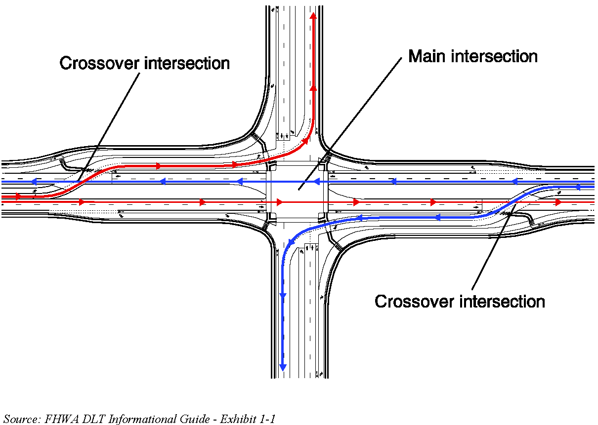
The DLT, also known as a continuous flow intersection (CFI) is an intersection that relocates one or more left turn movements on an approach to the other side of the opposing traffic flow. This allows left-turn movements to proceed simultaneously with the through movements and eliminates the left-turn phase for this approach. TxDOT has adopted the FHWA Displaced Left Turn Intersection Informational Guide9 as the primary source for DLT Guidelines. The information contained in this Appendix is considered a companion guide and is intended to document TxDOT’s suggested approach to DLT design. See Figure E-44 for a typical four-legged DLT with displaced lefts on a major street. (For a DLT 3 leg intersection reference Chapter 7 of the FHWA DLT Informational Guide)
Figure E-44. Four-legged DLT with Displaced Lefts on a Major Street
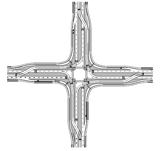
Benefits of a DLT include a reduction in the number of signal phases with a resultant increase in vehicle throughput. See Figure E-45 for an example of a DLT Intersection with displaced left turns on all approaches.
Figure E-45. DLT Intersection with Displaced Left Turns on All Approaches
Anchor: #i1006199Design Considerations
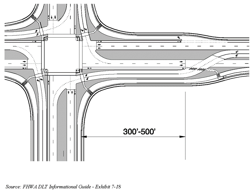
The distance between the main intersection and the crossovers should generally range from 300 to 500-ft. Shorter spacing may result in queue spillback and reduce the ability to clear queues through a single signal cycle phase. Longer spacing may result in greater difficulty in coordinating signal operations. See Figure E-46 for a depiction of typical intersection spacing.
Figure E-46. DLT Typical Intersection Spacing
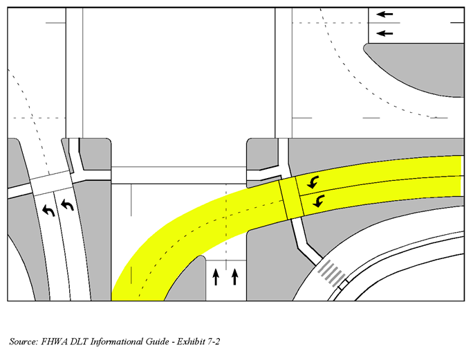
At the main intersection, the primary objective is to provide appropriate turning paths (typically a WB-67 in Texas) for the displaced left turns, considering the interaction with sidewalks. The vehicle paths for the displaced left turns through the main intersection will delineate the curb lines and stop bar locations and determine the width of the overall intersection as shown in Figure E-47.
Figure E-47. DLT Left-Turn Maneuvers
For the crossover intersection, the main objective is to provide a smooth alignment for the traffic and not introduce back-to-back reverse curves along the travel paths. The goal is to align the left turns at the stop bar with the receiving lanes to reflect desirable vehicle path alignment to minimize path overlap as shown in Figure E-48.
Figure E-48. DLT Crossover Intersection Geometry
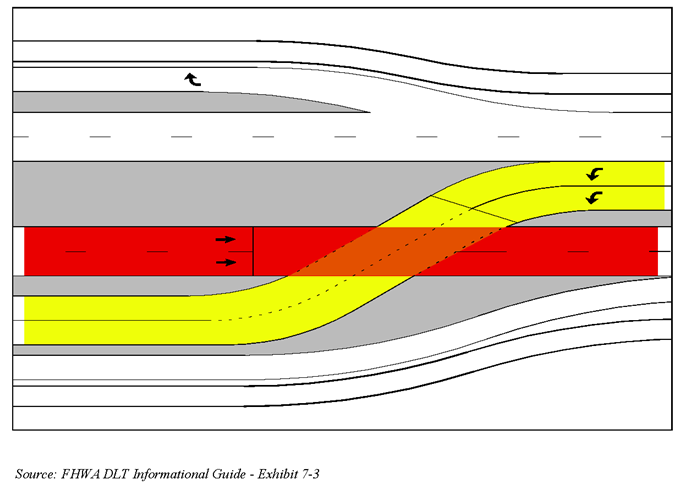
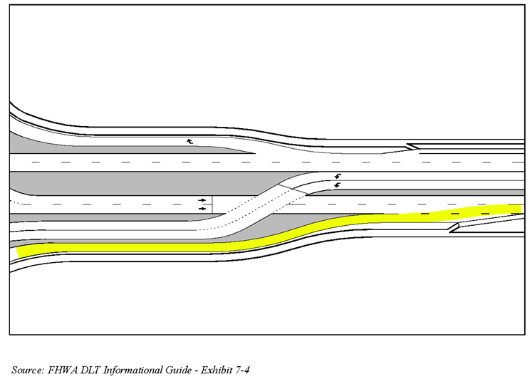
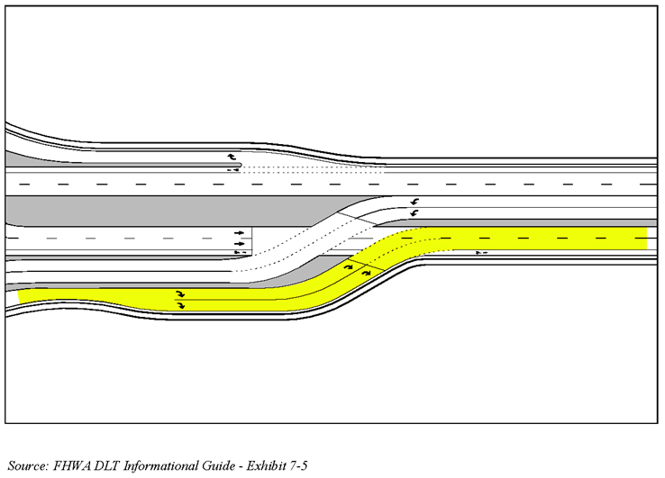
Additionally, there are two ways to accommodate the geometry where the right-turn bypass lane joins the cross road through lanes: 1) Provide an additional lane with a downstream merge, as shown in Figure E-49. 2) Signalize the movement and operate it as part of the crossover signal, as shown in Figure E-50.
Figure E-49. Add Lane with a Downstream Lane Merge
Figure E-50. Signalized Right Turn
Anchor: #i1006269Sight Distance
Provide appropriate sight distance and lighting for approaching motorists to see activity at the crosswalk, as well as sight distance for pedestrians to see oncoming traffic. Stopping sight distance for the approaching motorists and sight distances for the pedestrians approaching the potential oncoming automobiles must be clear of obstructions and provide sufficient visibility for various users.
Anchor: #i1006279Pedestrian and Bicyclist Considerations
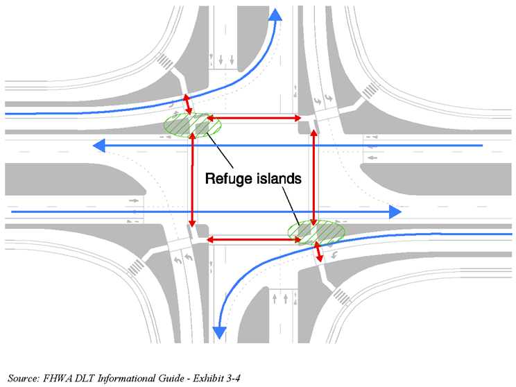
Crosswalks for DLTs are at the same locations that they would be for a conventional intersection. The major street crossing could be made in one or two stages, where the median can be used to provide a refuge for a two-stage crossing. Figure E-51 shows a typical pedestrian crossing with refuge islands.
Figure E-51. Refuge Islands Between Left-Turn and Through Lanes
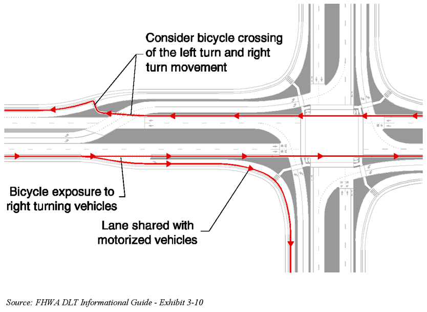
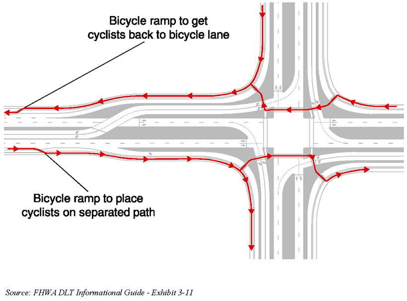
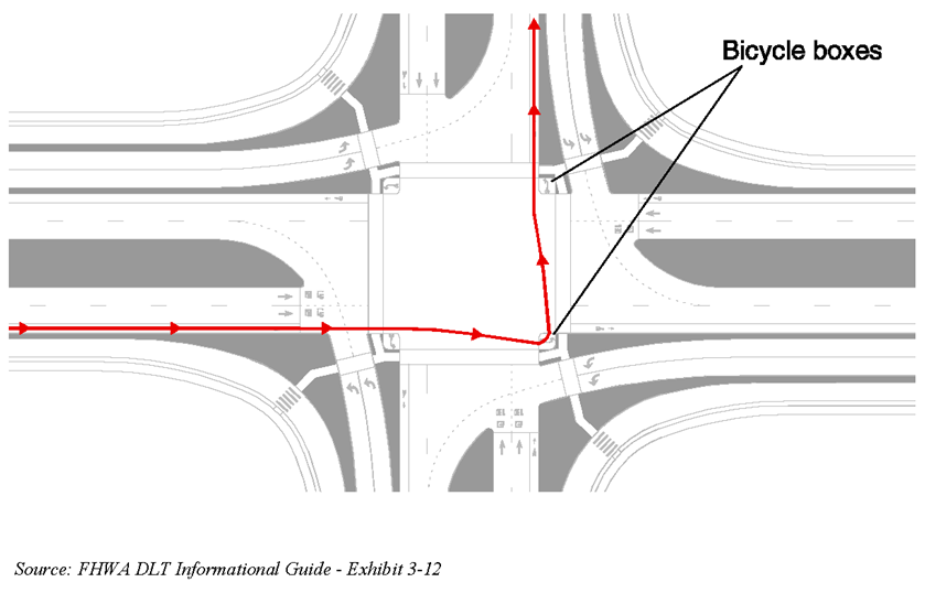
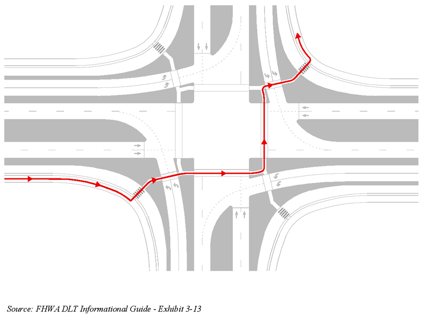
There are various options for bicyclists to use at a DLT; Figures E-52 and E-53 show options for bicycle through movements on and off street, respectively, and Figures E-54 and E-55 show options for bicycle left-turn movements on and off street, respectively. Ultimately, a thorough site assessment, an assessment of anticipated bicycle and pedestrian volumes, and an assessment of projected origins and destinations for pedestrians and bicyclists should be conducted to determine the preferred method of movement through the DLT
Figure E-52. Accommodating On-Street Bicycles Through a DLT Intersection
Figure E-53. Accommodating Off-Street Bicycles Through a DLT Intersection
Figure E-54. Accommodating On-Street Left-Turning Bicycles with a Bicycle Box Through a DLT Intersection
Figure E-55. Accommodating Off-Street Left-Turning Bicycles Through a DLT Intersection
Anchor: #i1006339Access Management
Maintaining or providing access to homes and businesses near a DLT intersection can be accomplished using frontage roads; however, the following operational impacts may result: Weaving movements in and out of driveways or U-turns (at the main or adjacent intersections) may be in conflict. DLT intersection implementation typically restricts access to parcels situated in the quadrants of the main intersection. Access to these parcels can be accommodated via right-in/right out from the channelized right-turn lanes. Reference the NCHRP Report 420 “Impacts of Access Management Techniques” for additional guidance for access management for DLT intersections.
