Section 8: Median Barrier
Anchor: #i1039085Overview
Median barriers are used to reduce median crossover vehicle encroachments and to protect against continuous longitudinal obstacles, and can generally be categorized as:
- Anchor: #PCYQTUDQ
- Concrete barriers (such as F-shape or single sloped); or Anchor: #JPSONEPP
- High-tension cable barrier systems.
The utilization of other median barriers, such as metal beam guard fence, may be appropriate based on the need to protect point obstacles in the median, such as overhead sign supports, etc. (See Sections 1-7).
Anchor: #i1039324Application
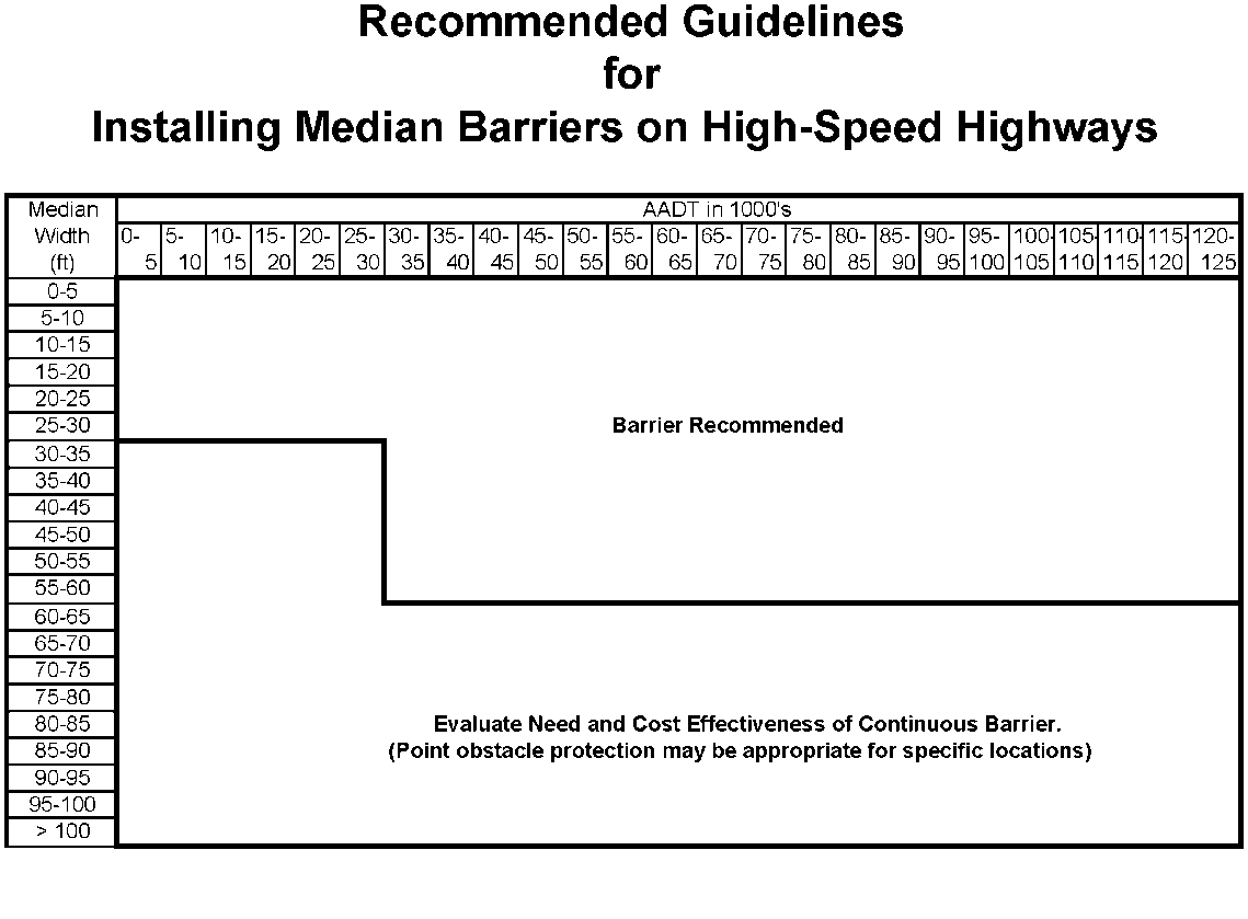
On high-speed highways, median barriers should be considered based on the criteria shown in Table A-3. Flush medians or frequent crossovers may preclude the use of median barriers based on an engineering analysis of individual locations.
The criterion is divided into two different zones by various combinations of average annual daily traffic and median width.
- Anchor: #JKQSGMEC
- Barrier Recommended: Barrier should be installed. Anchor: #ABFDJULW
- Evaluate Need and Cost Effectiveness
of Continuous Barriers. (Point obstacle protection may be appropriate
for specific locations): An engineering analysis should
be performed to determine if barrier is needed for reducing the
occurrence of cross-median encroachments (crashes). This analysis
may consider the following:
- Anchor: #WBOJTGPN
- Type of median (flush, depressed [V-ditch or flat-bottom]); Anchor: #BALRLDRW
- Width of the median (measured from edges of travel lane for opposing directions of travel); Anchor: #QQGWAPKB
- Traffic volumes, including estimated traffic growth and percent trucks; Anchor: #YIUYSDPG
- Types and severity of crashes; Anchor: #OQEIWHRW
- Posted speed limit; Anchor: #TLXUPFWM
- Type of facility, including controlled access or non-controlled access with crossovers; Anchor: #OTBJNBOM
- Roadway alignment; Anchor: #GIQKGCPU
- Ramp locations; and Anchor: #ESJSYAJK
- Elimination of barrier gaps.
Continuous barrier should be limited to areas where it is needed to reduce cross-median incidents and should not be used for point obstacles (i.e. overhead sign bridges, etc.), or in areas of lesser concern (i.e. wider medians, forested areas, etc.).
Anchor: #i1042298Placement
As a general rule, a barrier should be placed as far from the traveled way as possible while maintaining the proper operation and performance of the system. The more lateral offset afforded a driver, the better the opportunity for the driver to regain control of the vehicle in a traversable median and avoid a barrier impact. The placement of concrete barrier adjacent to narrow shoulders is discouraged. It is recommended that a minimum clear distance of 12-ft be maintained from the edge of the travel lane and a cable barrier to prevent incidental contact with the barrier being too close to the travel lane. Also, due to the deflection of the cable barrier, it is recommended that a minimum distance of 12-ft be maintained between the cable barrier and any obstruction being protected.
Slopes
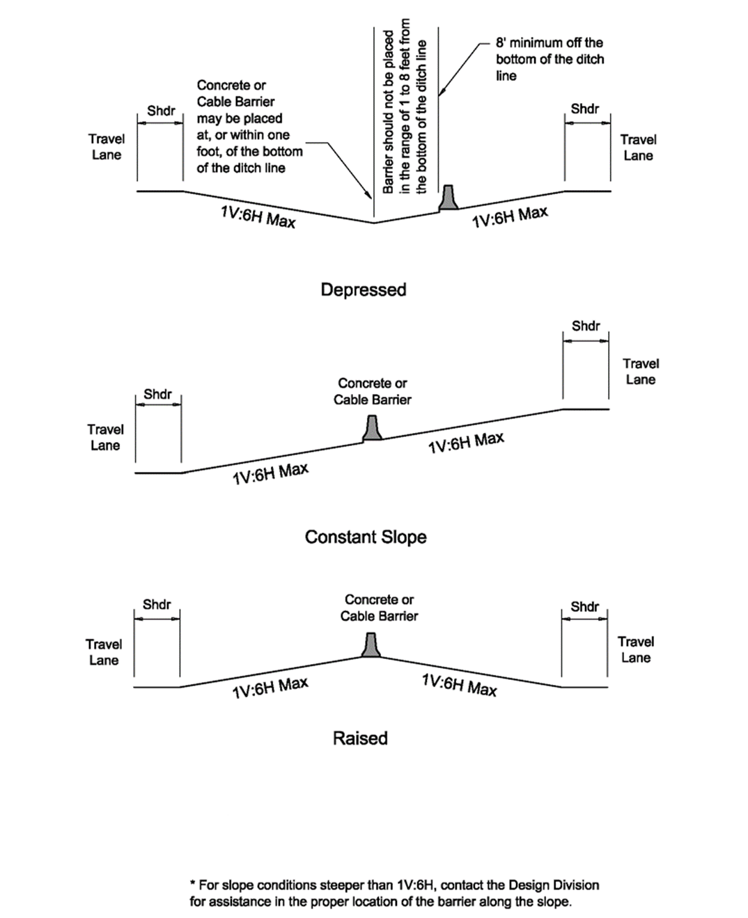
Where possible, barriers should be installed on relatively flat, unobstructed terrain (1V:10H or flatter). Barriers may also be placed on 1V:6H maximum slopes as shown in Figure A-15. The centerline axis of the barrier shall be vertical.
From the perspective of barrier performance alone, it is acceptable placement practice to locate the barrier at, or within 1-ft, of the bottom of the ditch line. If it is desirable to offset the median barrier more than one foot from the bottom of the ditch line to avoid drainage issues (potential for erosion, etc.), the barrier can be placed anywhere along the 1V:6H median slope, provided it is located at least 8-ft from the bottom of the median ditch line. This offset from the bottom of the ditch line reduces the potential for the vehicle striking the barrier too low for the barrier to function properly.
If the slopes in the median are steeper than 1V:6H and barrier is needed, consideration should be given to regrading the slopes to meet the requirements or to filling in the median to place a split-level concrete barrier.
If re-grading or other options are not feasible, placement of cable barrier on slopes up to 1V:4H is an alternative to consider. Contact the Design Division for assistance in locating the cable barrier at the proper location along slopes steeper than 1V:6H. While not desirable, some median configurations may require barrier placement on both sides of the median to provide the proper protection.
Figure A-15. Desirable Barrier Placement in Non-Level Medians.
Anchor: #i1060852Additional Cable Median Barrier Guidance
The cable barrier is for median use only and on medians greater than 25-ft. Median widths of 25-ft or less require the use of a more rigid barrier such as concrete median barrier.
The selection of Test Level 4 (TL-4) cable barrier over Test Level 3 (TL-3) cable barrier is at the district’s option. FHWA policy requires that all roadside appurtenances such as traffic barrier and barrier terminals used on the National Highway System (NHS) meet the performance criteria contained in the National Cooperative Highway Research Program (NCHRP) Report 350, Recommended Procedures for the Safety Performance Evaluation of Highway Features or the updated testing procedures found in The Manual for Assessment of Safety Hardware (MASH). Safety features approved to a minimum TL-3 are acceptable for highspeed arterial highway. Any decision to use TL-4 tested barrier should be made based on-site conditions and traffic mix, using engineering judgement.
The vertical alignment of the system is essential since the location of the bottom cable with respect to the ground is critical to capturing smaller vehicles. Special attention should be placed on sag vertical alignments. The cables and/or posts placed in sockets are free standing (not held down by the system) and will come to a taut elevation between two tangent points when the cable is tensioned creating a larger distance from the ground line to the bottom cable than allowed by the manufacturer’s installation manual. Sag vertical alignments with radii of less than a K-Value of 11 should be avoided.
The placement of the system should also take into consideration the drainage facilities located in the median. Cross drainage structures with less than 36-in of cover pose a challenge for placing posts. Structures of less than 16-ft can be spanned and construction of these runs of cable should take these structures into account prior to setting post locations.
If an obstruction is currently protected by MBGF and there will be minimum of 12-ft clearance from the proposed cable barrier to the obstruction, the MBGF may be removed. If there is less than 12-ft clearance from the proposed cable barrier to the obstruction, it is recommended that the MBGF be left in place, and the cable barrier be placed such that there is a minimum of 4-ft (5-ft preferred) from the back of the MBGF posts to the barrier. This allows for deflection of the MBGF without engaging the cable barrier. Cable barrier should be a minimum 5-ft behind SGT’s to allow for extrusion and gating of the end treatment.
Cable barrier systems deflection is based on it being installed along a tangent or when struck on the “concave” side (from the inside of a curve). When it is struck in the “convex” side (from the outside of the curve) the barrier must deflect enough to redevelop a concave condition. Placement of the barrier on the convex side is also recommended to allow maximum median availability for deflection (see Figure A-16). In order to minimize the length over which this occurs, closer post spacing through these curves is recommended (see Table A-4).
Figure A-16. Desirable Cable Barrier Placement in a Curve.
|
Radius (ft) |
Post Spacing |
|---|---|
|
650-2,500 |
6-ft, 8-in |
|
2,501-5,500 |
10-ft |
|
> 5,500 |
Standard Recommendation |
A recommended maximum run of cable barrier between anchors should be approximately 10,000-ft. This length allows for proper tensioning of the system and reasonable construction installation time to get a run-in operation. Runs of shorter and longer lengths between anchors may be appropriate in specific locations and each run should be determined to meet the field situations.


