Section 2: Roundabouts
Anchor: #i1005174Overview
A roundabout is a form of a circular intersection in which traffic travels counterclockwise around a central island and entering traffic yields to the circulating traffic. Roundabouts have been demonstrated to significantly reduce the number of severe crashes at intersections, improve Level of Service (LOS), and increase capacity. TxDOT has adopted NCHRP Report 672 (Roundabouts an Informational Guide, 2nd Edition) as the primary source for roundabout design guidelines. The information contained in this Appendix is considered a companion guide to NCHRP Report 672, and is intended to document TxDOT’s suggested approach to roundabout design.
Anchor: #i1005187Planning
During the planning stage many considerations are needed to determine the applicability of a roundabout, including ROW, utilities, access management, operations of adjacent intersections, safety impacts, existing and predicted future traffic volume, public education, and public outreach. Locations that meet or nearly meet a signal warrant(s) should be given consideration for roundabout installation. Intersections that are, or proposed to be, all-way stop control may also be good candidates for a roundabout. Figures E-1 through E-4 show the design characteristics and features of the three roundabout categories: Mini-roundabout, Single Lane Roundabout, and Multilane Roundabout.
Figure E-1. Design Characteristics of Three Roundabout Categories
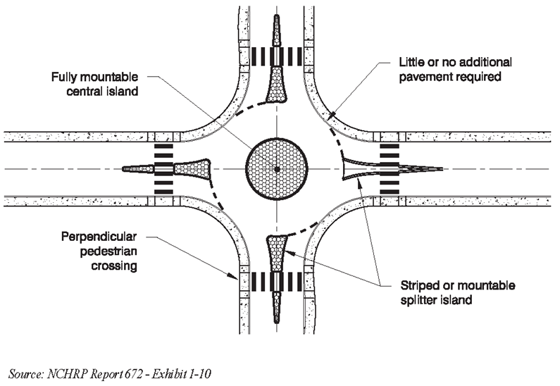
Figure E-2. Features of a Typical Mini-Roundabout
Figure E-3. Features of a Typical Single-lane Roundabout
Figure E-4. Features of a Typical Two-lane Roundabout
The preference in Texas is to utilize a single lane roundabout as long as possible to avoid unnecessarily overbuilding the roundabout. Experience shows that most roundabouts that are redesigned are actually reduced in size (e.g., 2 to 1 lane). In some instances, the reduction of lanes was done to diminish minor crash patterns5. If a single lane roundabout is found to be adequate for up to 10 years after the opening year, a single lane roundabout should be constructed. If a multilane roundabout is required before the design year (20 years after opening year), the single lane roundabout should be constructed having the footprint of a multilane roundabout and be designed to be easily retrofitted to a multilane roundabout when needed. For multilane roundabout designs, additional independent reviews are recommended by designers with expertise in roundabout design.
Anchor: #i1005240Geometric Design
The primary goals of any roundabout design are to provide:
- Anchor: #BCPUBFTD
- Slow entry and
consistent speeds throughout the roundabout by using deflection.
-
Anchor: #UHFRWEQV
- Deflection can be achieved by providing a curvilinear path upon entry into the roundabout to help control entry speeds. This will force drivers to enter at slow speeds and promote consistency in speeds between traffic entering, circulating, and exiting the roundabout.
Anchor: #FBEJRNAW - The appropriate number of lanes and lane assignment to achieve capacity, lane volume balance, and lane continuity. Anchor: #UHCBPOGF
- Smooth channelization that result in vehicles naturally using the intended lanes. Anchor: #UPXRLNJY
- Adequate accommodation for the design vehicles. Anchor: #CUWEHDVG
- Safe accommodations for pedestrians and bicyclists. Anchor: #QPTOCJQW
- No more than the minimum intersection sight distance for driver recognition of the intersection and conflicting users.
The two most relevant aspects of sight distance for roundabouts are stopping sight distance and intersection sight distance. Stopping sight distance must be provided at every point within a roundabout, and on each entering and exiting approach. At roundabouts, the only locations requiring evaluation of intersection sight distances are the entries. A combined sight distance diagram should be overlaid onto a single drawing to illustrate the clear vision areas for the intersection. Chapter 6 of NCHRP Report 672 provides specific guidance with respect to sight distance determination and application.
The design vehicle is the largest vehicle likely to use the alternative intersection; this is typically a WB-67 vehicle in Texas (a smaller design vehicle may be used for urban/local or suburban classifications). The anticipated truck movements through the roundabout should be determined in AutoTURN, AutoTrack, or a similar tool used to determine vehicle encroachment within the roundabout. Currently there is research underway to update the vehicle turning movement templates since they are decades old and tend to be overly conservative. If a significant number of large trucks is anticipated through an intersection, it is advisable to find an area where the wheel paths of the respective design vehicle could be physically tested and documented. The largest truck movements may be accommodated by using a truck apron (with a roll down curb) within the central island. The apron provides additional paved surface for the design vehicle while keeping the actual circulatory roadway width narrow enough to maintain speed control for smaller passenger cars. The basic geometric elements of a roundabout and typical inscribed circle diameters are shown in Figures E-5 and E-6:
Figure E-5. Basic Geometric Elements of a Roundabout
Figure E-6. Typical Inscribed Circle Diameter Ranges
Anchor: #i1005308Entry Width
The entry width is determined by the design vehicle entering the roundabout. For single-lane entrances a typical range for entry width would be from 16 to 20-ft. A 17-ft entry width would be considered a good starting point. Entry widths greater than 20-ft often confuse drivers into thinking there are two lanes available when there is only one circulatory lane in the roundabout. Chapter 6 of NCHRP Report 672 provides additional information on entry widths for roundabouts.
Anchor: #i1005318Circulatory Roadway Width
The circulatory width is generated from the number of lanes entering the roundabout and the turning movements of the design vehicle. For single-lane roundabouts, an 18 to 20-ft circulatory roadway width would be typical. For two-lane roundabouts, it may be necessary to accommodate turning movements for one of the following:
- Anchor: #TNYDTROH
- Two passenger vehicles side by side assuming infrequent traffic from semi-trailers; Anchor: #NVHVWFRM
- A passenger vehicle and single unit truck side by side; Anchor: #CGEUCEMV
- Where semi-trailer traffic is greater than 10 percent of the overall traffic, a semi-trailer in conjunction with a passenger vehicle or single unit truck.
Chapter 6 of NCHRP Report 672 provides additional information on circulatory roadway widths for roundabouts.
Anchor: #SHWRGPBDEntry Curve
Capacity and safety are both impacted by the determination of the entry curve radius. Large entry curves may generate relatively fast entry speeds, and reductions in capacity are generally noticed with entry curves less than 50-ft. Entry curves with a radius of 50 to 100-ft are typical for an urban single-lane roundabout. Entry radii from 70 to 85-ft would be a good beginning point for determining the entry radius of a multilane roundabout. Chapter 6 of NCHRP Report 672 provides additional information on entry curves for roundabouts.
Anchor: #i1005338Exit Curve
The exit curve design is controlled by conditions such as pedestrian traffic, whether it is an urban roundabout or a rural roundabout, and geometric limitations. In order to avoid congestion and crashes at the exit point in a roundabout, exit curve radii are typically greater than entry curve radii. Exit curve radii of 200 to 400-ft is recommended to promote proper tangent alignment from the circulatory to the exit. Larger trucks are more easily accommodated by larger exit curve radii.
Anchor: #i1005348Roundabout Speeds
The most critical design objective for a roundabout is to maintain low and consistent speeds at the entry and throughout the roundabout. Horizontal curvature and reduced pavement widths influence low speed conditions in roundabouts. The maximum entering design speeds based on a theoretical fastest path are: Mini-Roundabout – 20 mph; Single Lane – 25 mph; Multilane – 25 to 30 mph. See Figure E-7 and Figure E-8 for depictions of the fastest vehicle path through a single lane-lane roundabout and a multilane roundabout, respectively. See Chapter 6 of NCHRP Report 672 for recommended horizontal curvatures and pavement widths to produce proper speeds.
Figure E-7. Fastest Vehicle Path through Single-lane Roundabout
Figure E-8. Fastest Vehicle Path through Multilane Roundabout
See NCHRP Report 672 for additional discussion on roundabout geometric guidance.
Anchor: #i1005381Vertical Geometry
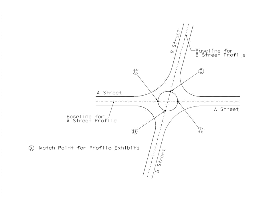
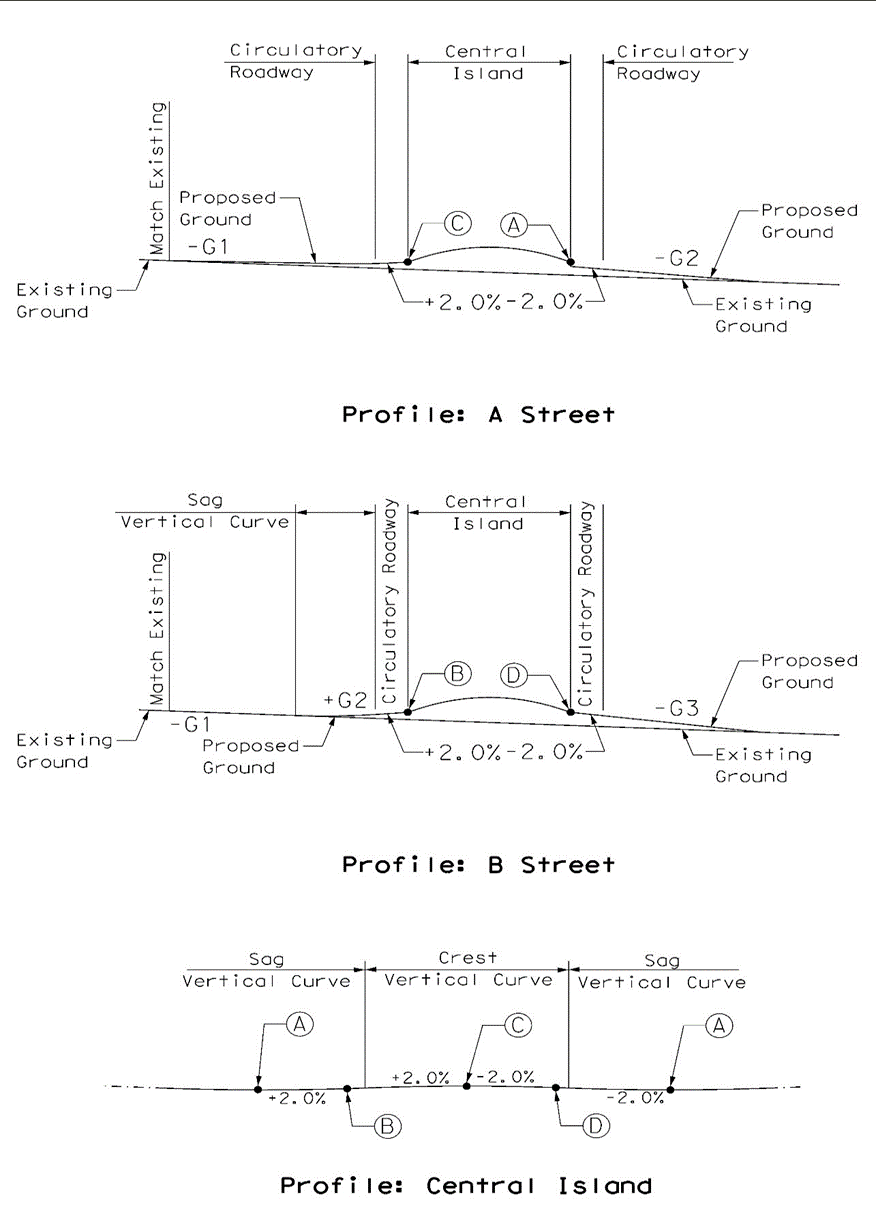
In forming the vertical geometry for a roundabout, a thorough investigation of the approach roadways and central island profile is needed. The approach roadway profiles should connect to the profile for the circumference of the central island. The vertical geometry for the circumference of the central island is typically a sine curve. Examples of vertical geometry for roundabouts are shown in Figures E-9 and E-10. Note that cross slopes and/or truck apron slopes may be less than those shown in the examples to further accommodate low boy type vehicles.
Figure E-9. Sample Central Island Profile
Figure E-10. Sample Central Island Profile
NOTE: All grades shown are examples.
Anchor: #i1005404Cross-Slope
The typical cross-slope for a roundabout is an outward 2 percent slope from the central island. Note that the cross slope may be less than 2% to further accommodate lowboy type vehicles.
Anchor: #i1005415Splitter Islands
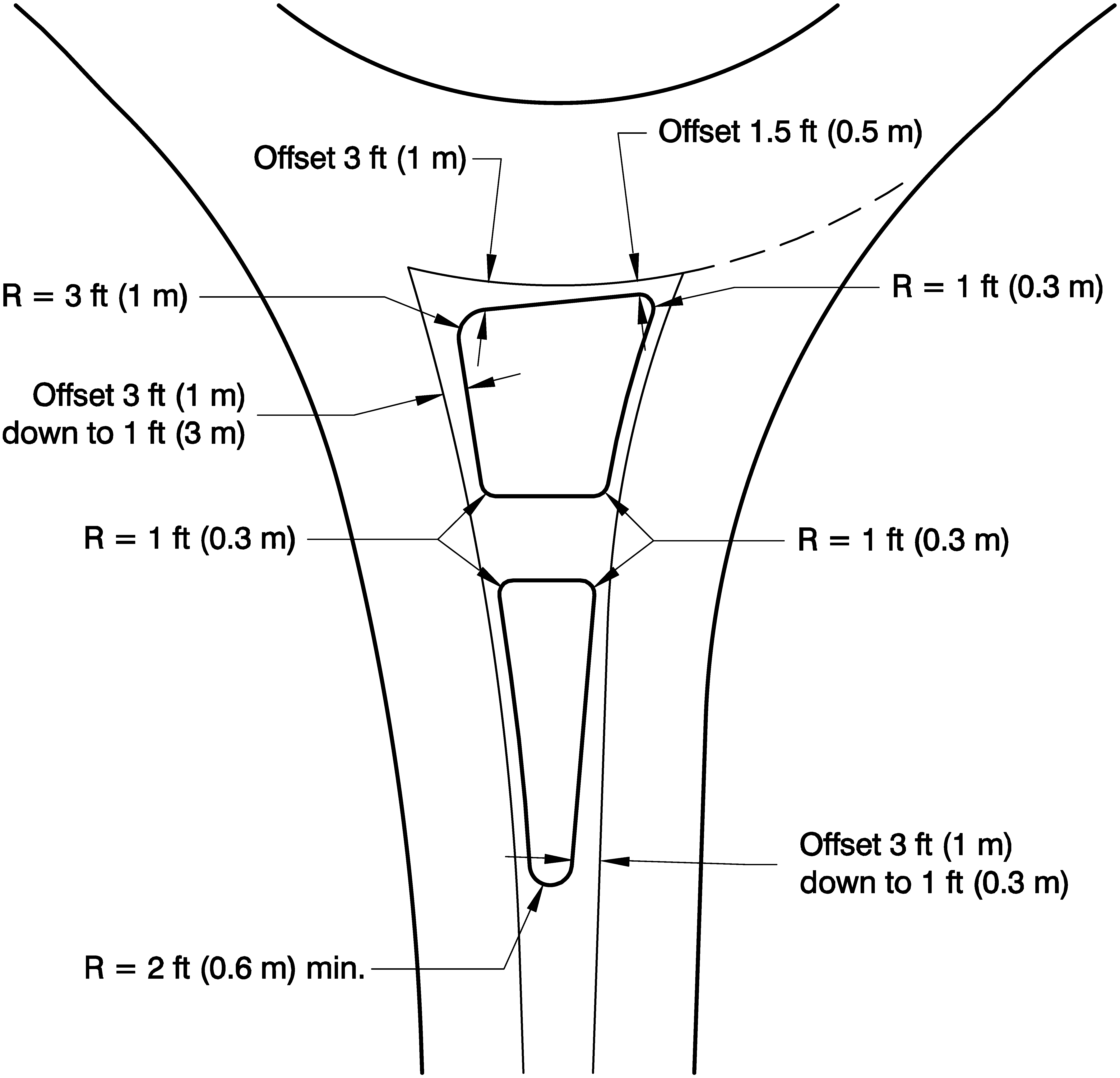
AASHTO standard guidelines govern the design of the splitter island. See Figure E-11 for minimum values for nose radii and offsets. Note that larger radii than those specified in the minimums are recommended in order to avoid the breaking off of curbs.
Figure E-11. Minimum Splitter Island Nose Radii and Offsets
Anchor: #i1005434Pedestrian Considerations
Roundabouts can provide benefit to pedestrians through reducing the number of potential conflict points with vehicles. However, roundabout entrances/exits are uncontrolled crossings for pedestrians, and designers should consider treatments in this light. Pedestrian street crossings at roundabouts can be difficult to identify for pedestrians with vision disabilities because the crossings are located to the side of the pedestrian circulation path around the street or highway.
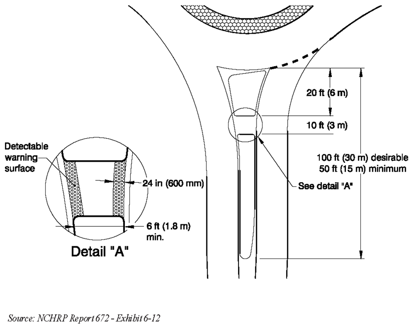
Pedestrians should be considered and accommodated at all roundabout intersections. In some situations (such as rural intersections), pedestrian accommodations may not be necessary; however, it is recommended that splitter islands be designed to be wide enough to accommodate potential future crossings of pedestrians. By providing refuge on the splitter island, the pedestrians cross only one direction of conflicting traffic at a time. The minimum dimensions of the splitter islands are shown in Figure E-12 (Note that the 6-ft measured in Detail “A” is from back of curb to back of curb). Wherever possible, sidewalks at roundabouts should be set back from the edge of the circulatory roadway with a landscape strip. Further information for the design of general pedestrian accommodations for roundabouts is provided in NCHRP Report 672, Section 6.8.1.
Figure E-12. Minimum Splitter Island Dimensions
Considerations
Truck aprons (refer to Chapter 7 Section 3.6.3.3) can help achieve desired deflection for reducing vehicle speeds, while accommodating large vehicles in roundabouts as well as within the approach and departure lanes to the roundabouts.
Single-Lane Roundabouts
If a single-lane roundabout is located in an urban area with high expected pedestrian and vehicle traffic, consider an activated crossing beacon for pedestrians.
Multilane Roundabouts
Pedestrian facilities at multilane roundabouts should be more proactively considered and designed to help pedestrians navigate safely and comfortably. Designs with multilane exits create the greatest issues for pedestrians as they share the same multiple conflict points as a stop and yield condition midblock crossing. Drivers exiting the roundabout, though slowed by deflection of the center island and roadway edge, may not have adequate stopping distance to accommodate pedestrians entering the roadway.
Multilane roundabouts can be problematic for pedestrians with vision disabilities. Specifically, they may have difficulty detecting gaps and determining that motorists have stopped and yielded. To improve pedestrian safety, pedestrian-activated beacons, signals, or raised crosswalks may be considered at all multilane roundabout entries and exits. Detectable edging or barriers must be provided where pedestrian crossings are not intended (refer to Chapter 7 Section 3.4.4).
Anchor: #i1044041Bicyclist Considerations
Roundabouts also provide additional safety for bicyclists due to the slower vehicular speeds which result in less of a speed differential between bicyclists and motor vehicles since typical on-road bicycle speeds are between 10 and 20 mph. Bicyclists will typically take a full lane to traverse the roundabout. Less experienced bicyclists may also have the option of choosing to travel on the sidewalks provided for pedestrians and bicyclists at the roundabout. In these instances, slip ramps (which is a type of ramp for getting bicyclists from the roadway onto the sidewalk) should be considered. Chapter 6 of NCHRP Report 672 provides additional specific guidance with respect to bicycle design at roundabouts.
Anchor: #i1005458Access Management
Access management is central to the proper functioning of a roundabout from an operational and safety standpoint. Avoid locating driveways with direct access to a roundabout. If unavoidable, NCHRP Report 672 provides guidance on situations where driveways may be allowed direct access. Additionally, access points near a roundabout have restricted operations due to the channelization of the roundabout. The ability to provide full access is governed by the following factors:
- Anchor: #OPOSNVFF
- The capacity of the minor movements at the access point. Anchor: #EIHRFQGT
- The need to provide left turn storage downstream of the roundabout on the major street to serve the access point in order to prevent blocking the major street flow. Anchor: #QAMUNQJN
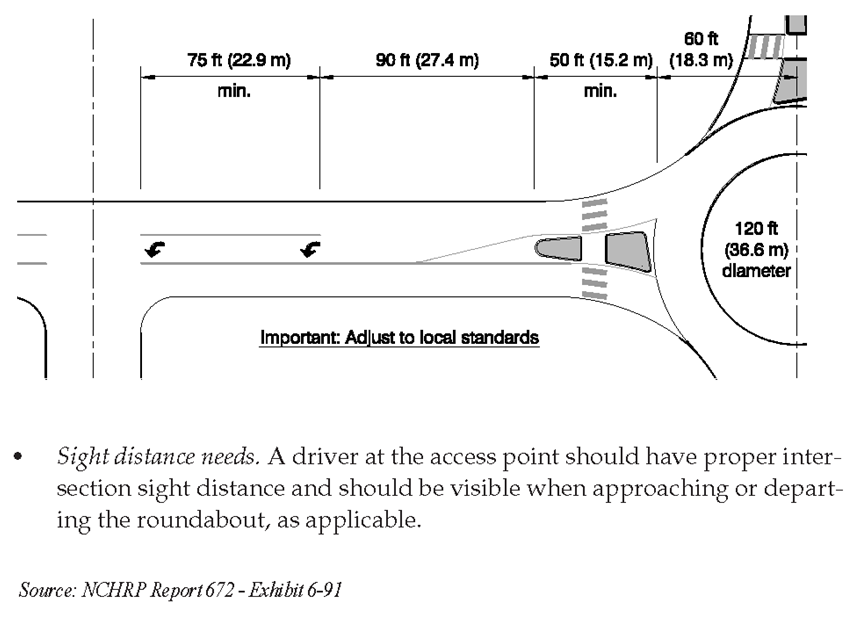
- The available space between the access point and the roundabout in order to allow for adequate splitter island design and left-turn pocket channelization (see Figure E-13 for an example). Note the resulting storage and taper length should be analyzed using the anticipated turning volume into the driveway to avoid queue spillback into the roundabout. Anchor: #UFSPCYBB
- Sight distance needs.
Figure E-13. Typical Dimensions for Left-turn Access near Roundabouts
Reference NCHRP Report 672 for additional guidance with respect to access management at roundabouts.

