Appendix B: Treatment of Pavement Drop-offs in Work Zones
Anchor: #CHDGAEIESection 1: Overview
Anchor: #i1002243Scope
These guidelines apply to construction zone work where continuous pavement edges or drop-offs exist parallel and adjacent to a lane used for traffic. These guidelines do not apply to short-term operations. The Texas Manual on Uniform Traffic Control Devices (TMUTCD) defines short-term operations as daytime work from one to twelve hours.
These guidelines do not constitute a rigid standard or policy; rather, they are guidance to be used in conjunction with engineering judgment.
Anchor: #i1002261Types of Treatment
Treatment may consist of either or both of the following:
- Anchor: #UBNFNXVU
- Warning devices (such as signs or channelizing devices), and Anchor: #QMDSUAQJ
- Protective barriers (such as concrete traffic barriers or metal beam guard fence).
Factors Affecting Treatment Choice
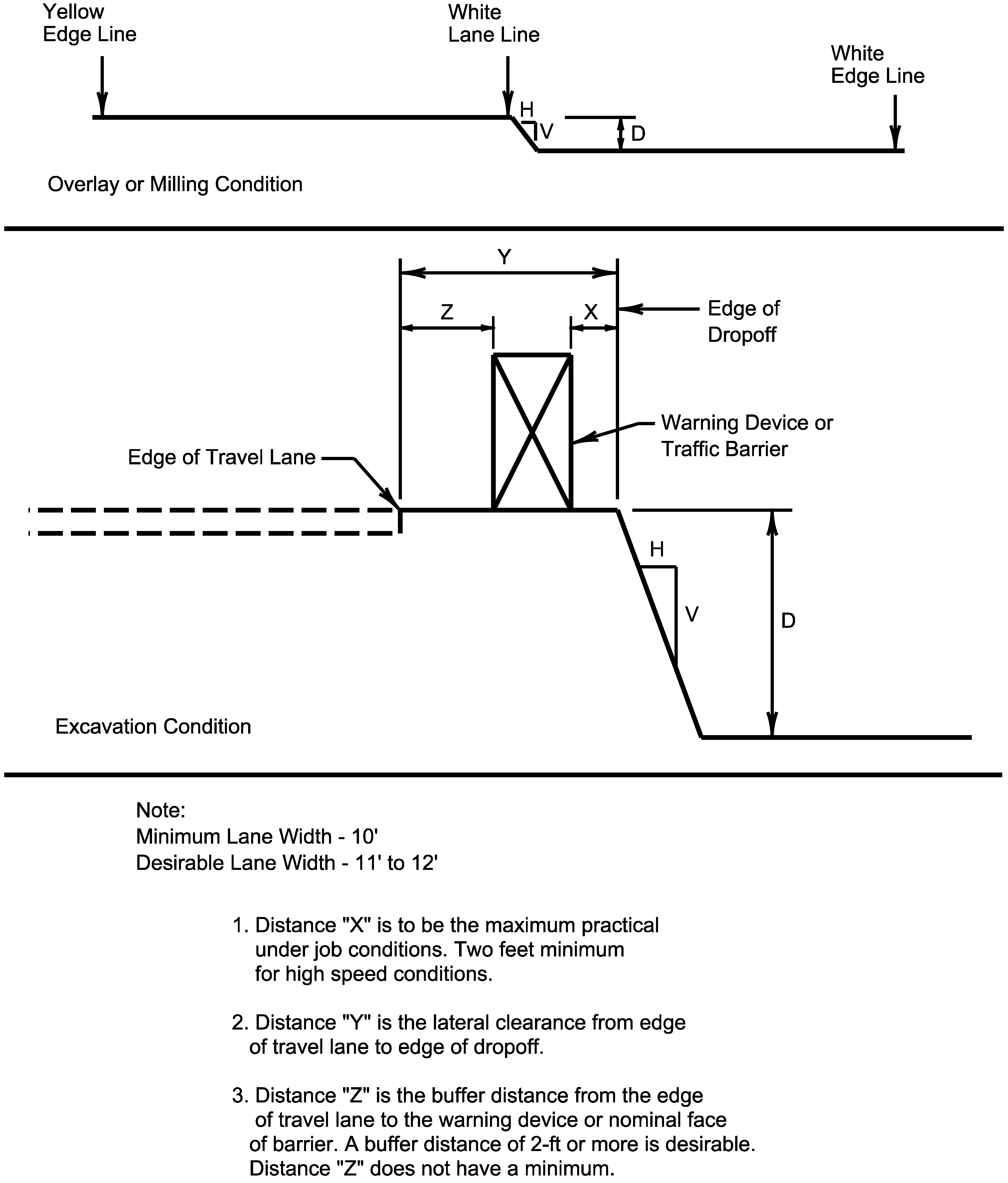
The type of treatment (warning device or protective barrier or both) selected depends on several factors, including engineering judgement. These guidelines are based on the factors presented in Table B-1.
|
Factor |
Definition |
Notes |
|---|---|---|
|
Edge condition |
Slope of the drop-off |
For more information, see “Edge Condition” subheading below. |
|
Lateral clearance |
Distance from the edge of the travel lane to the edge condition |
See Figure B-1 for description. |
|
Edge height |
Depth of the drop-off |
See Figure B-1 for description. |
Figure B-1. Definition of Terms.
In addition to the factors considered in the guidelines, each construction zone drop-off situation should be analyzed individually, taking into account other variables, such as:
- Anchor: #YTGIGLKW
- Traffic mix; Anchor: #CKYYIAXB
- Posted speed in the construction zone; Anchor: #YWWLCMOJ
- Horizontal and vertical curvature; Anchor: #IAEBKAJM
- Practicality of treatment options; Anchor: #OSVOVLHA
- Driveways and access; Anchor: #WPBHJWTK
- Safety impacts and crash history; and Anchor: #VQENVJRN
- Illumination. Anchor: #NEMMQFTK
-
In urban areas where speeds of 30 mph or less can be predicted for traffic in a particular construction zone, there may be a lesser need for signing, delineation, and barriers. Regardless, sharp 90-degree edges greater than 2-in in height, if located within a lateral offset distance of 6-ft or less from a traffic lane, may indicate a higher level of treatment.
If distance Y (as described in Figure B-1) is less than 3-ft, use of positive barrier may not be feasible. In such a case, if a positive barrier is required (according to Figure B-2), then consider one of the following:
Anchor: #XLTDOFKS - Moving the lane of travel laterally to provide the needed space, and Anchor: #XXDXYGFF
- Providing an edge slope such as Edge Condition I.
Edge Condition
“Edge condition” refers to the slope of the drop-off. Table B-2 describes three edge condition types used in these guidelines. These edge conditions may be present between shoulders and travel lanes, between adjacent or opposing travel lanes, or at intermediate points across the width of the paved surface. Due to the variability in construction operations, tolerances in the dimensions shown in the figures may be allowed by the engineer.
|
Condition Type & Description |
Notes |
|---|---|
|
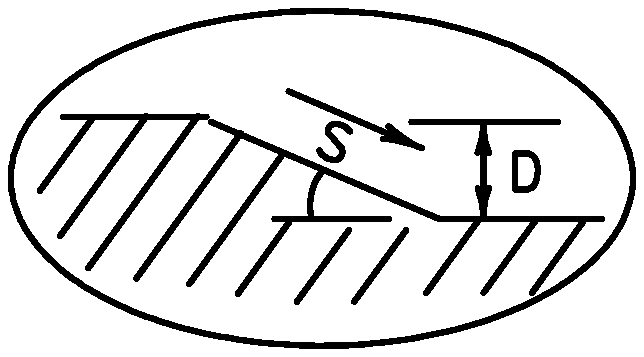
Edge Condition I S = 3:1 or flatter slope rate (H:V) |
Most vehicles are able to traverse an edge condition with a slope rate of 3 to 1 (horizontal to vertical) or flatter. The slope must be constructed with a compacted material capable of supporting vehicles. |
|
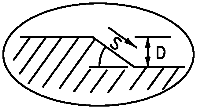
Edge Condition II S = 2.99:1 to 1:1 slope rate (H:V) |
Most vehicles are able to traverse an edge condition with a slope between 2.99 to 1 and 1 to 1 (horizontal to vertical) as long as D does not exceed 5 inches. Undercarriage drag on most automobiles will occur as D exceeds 6 inches. As D exceeds 24 inches, the possibility of rollover is greater for most vehicles. |
|
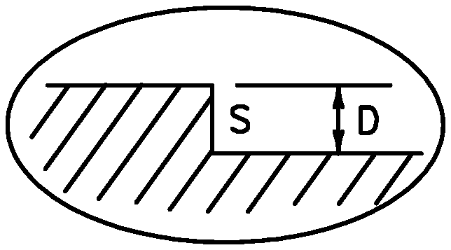
Edge Condition III S is steeper than 1:1 slope rate (H:V) |
Slopes steeper than 1 to 1 (horizontal to vertical) where D is greater than 2 inches can present a more difficult control factor for some vehicles, if not properly treated. For example, in the zone where D is greater than two and up to 24 inches, different types of vehicles may experience different steering control at different edge heights. Automobiles might experience more steering control differential in the greater than 2 and up to 5 inch zone. Trucks, particularly those with high loads, have more steering control differential in the greater than 5 and up to 24 zone. As D exceeds 24 inches, the possibilities of rollover are greater for most vehicles. NOTE: Milling or overlay operations that result in Edge Condition III should not be in place without appropriate warning treatments, and these conditions should not be left in place for extended periods of time. |
Anchor: #i1002361
Guidelines for Treatment
The “Treatment for Various Edge Conditions” standard sheet shows the treatments for given combinations of edge condition, lateral clearance, and edge height. Remember to consider other factors listed above and use engineering judgment. The standard sheet requires the Engineer's seal, signature, and date.
Edge drop-offs greater than 2-in immediately adjacent to traffic should not be left overnight.
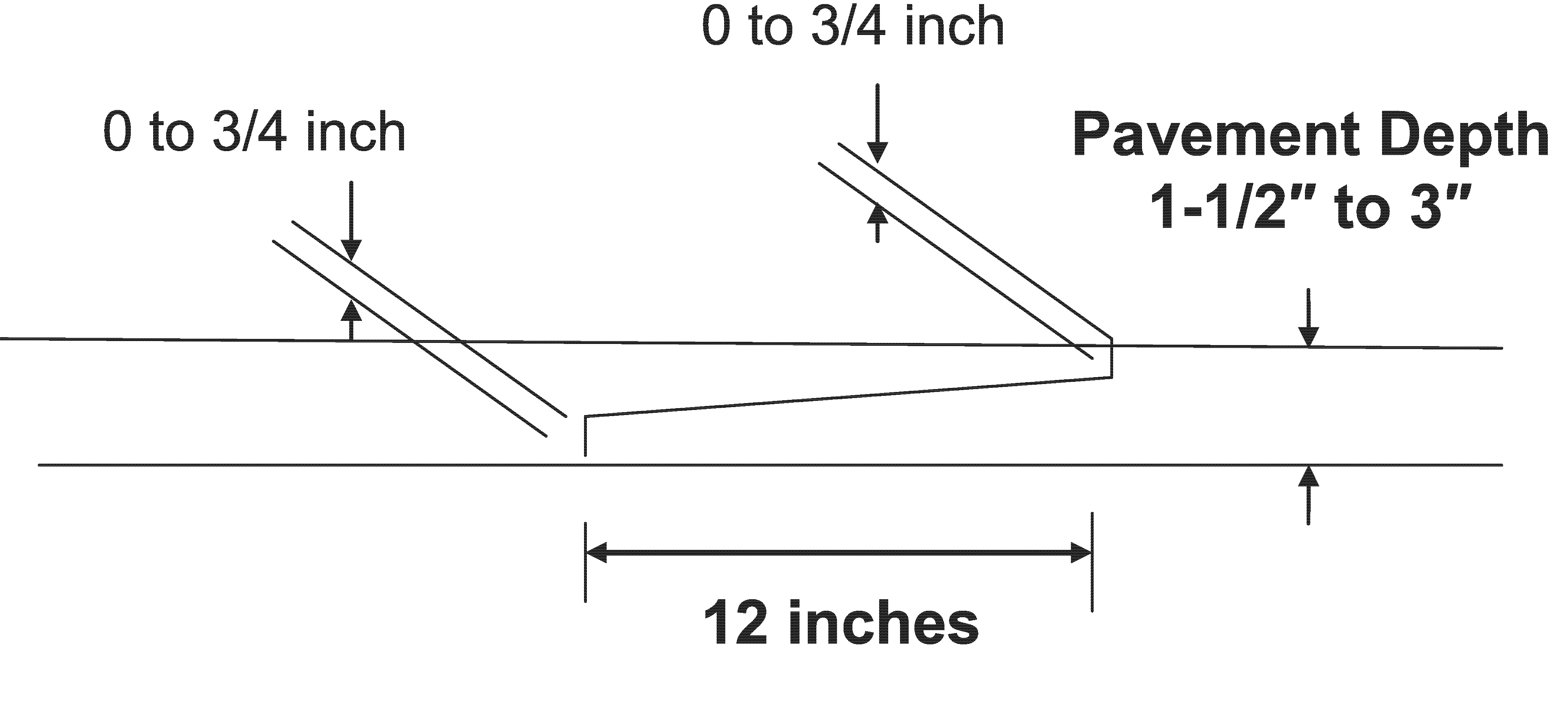
Careful consideration should be given to allowing 1-in to 2-in vertical longitudinal joints between lanes or directly adjacent to the travel lane. Vertical joints greater than 1-in are particularly challenging for motorcyclist and bicyclists to traverse. If a 2-in vertical longitudinal joint is to be used in or adjacent to traffic, consider using the notched-wedge joint as shown in Figure B-2.
Figure B-2. Notched-Wedge Joint Detail.
Refer to the Construction Divisions technical advisory report on Use of Tapered Longitudinal Joints such as the Notched Wedge Joint for additional information.
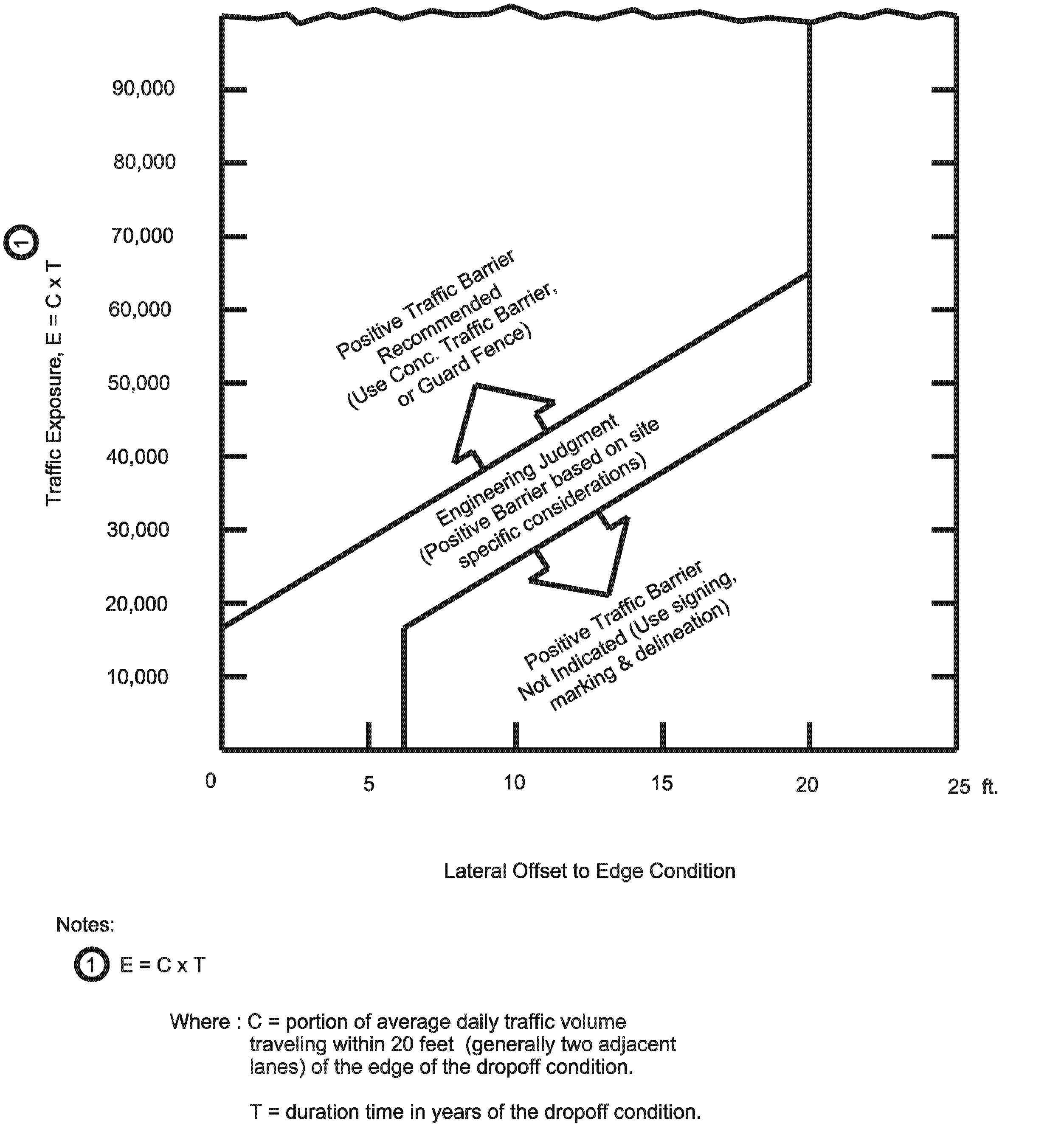
Figure B-3 depicts the relationship between the lateral offset to the edge condition, its exposure to traffic, and when positive barrier should be considered. The use of the pavement drop-offs treatment guidelines along with Table B-1, Table B-2, Figure B-1, and Figure B-3, provides a practical approach to the use of positive barriers for the protection of vehicles from pavement drop-offs. Other factors, such as the presence of heavy machinery, construction workers, or the mix and volume of traffic, may make positive barriers appropriate, even when the edge condition alone may not justify the barrier.
NOTE: An approved end treatment should be provided for any positive barrier end located within the clear zone.
Figure B-3. Conditions Indicating Use of Positive Barrier.
