Section 4: Guide Sign Assemblies
Anchor: #i1004280Introduction
This section describes the purpose of several different types of conventional guide sign assemblies. These assemblies include:
- Anchor: #VTPTFCWE
- Junction Assembly: Provides advance notice of an intersection with another highway. Anchor: #SLGXSQSS
- Advance Route Turn Assembly: Provides advance notice that a turn is necessary to remain on the indicated highway. Anchor: #GKFKQHLP
- Directional Assembly: Provides directional information about one or more highways at an intersection. Anchor: #YBOUQVMG
- Confirming or Reassurance Assembly: Provides confirmation information about the highway after passing through the intersection. Anchor: #EDYNLFWN
- Trailblazer Assembly: Provides directional information to a highway not located at the current intersection.
Elements associated with each type of assembly are addressed in this section. The placement of assemblies is addressed in Chapters 5 and 6.
Anchor: #i1004320Junction Assembly (Texas MUTCD Section 2D.30)
Purpose: A Junction Assembly is used to provide advance notice of an intersection with another highway. Junction signs are located in advance of intersections where a marked route is intersected or joined by another marked route.
Components: The following components make up a Junction Assembly:
- Anchor: #NWCPFCKA
- Standard: Junction auxiliary sign and route sign. Anchor: #BTHRHSSA
- Optional: Cardinal Direction auxiliary sign, Lane Designation auxiliary sign, and Distance plaque.
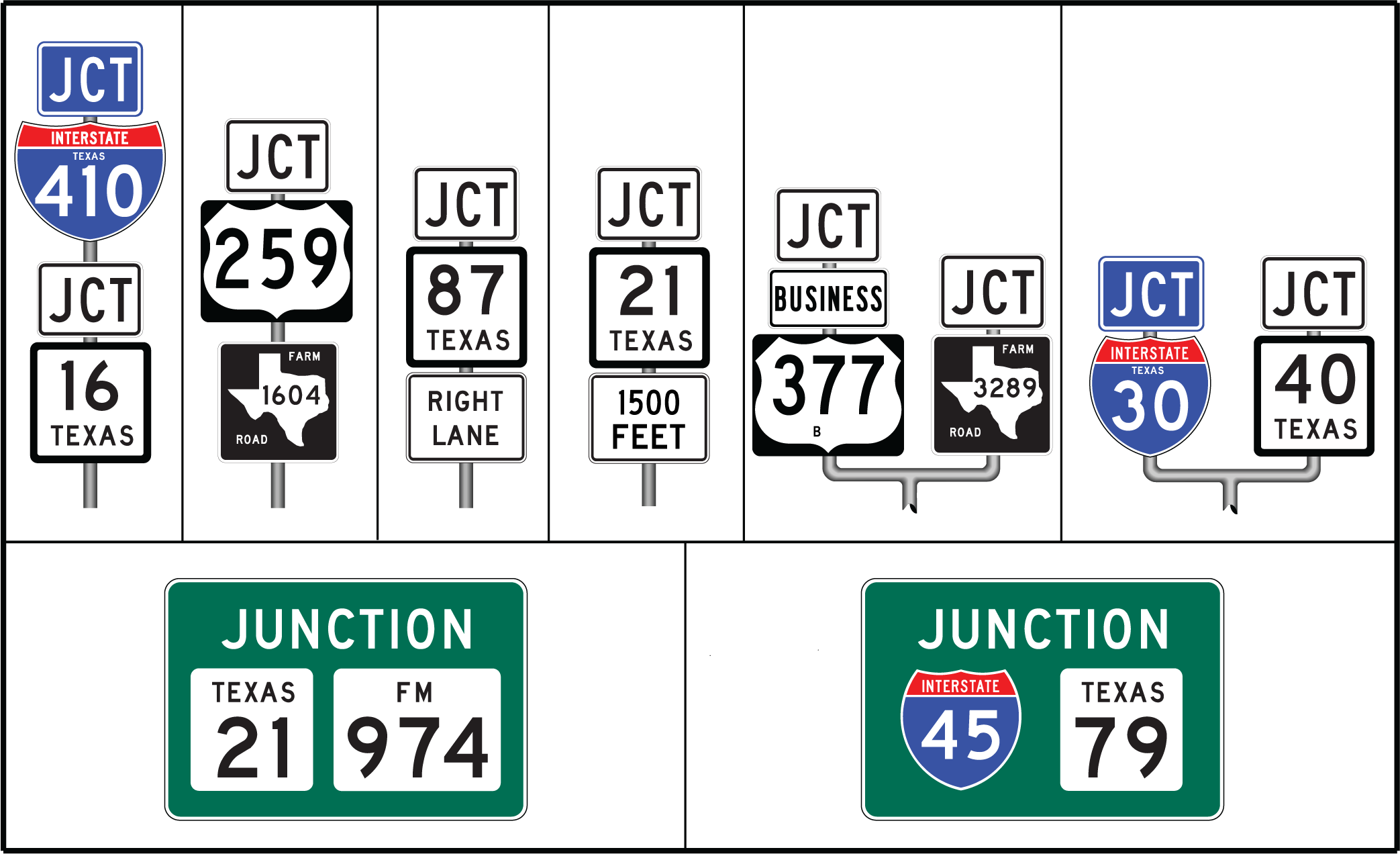
Where two or more routes are to be indicated, one Junction sign can be used with both route signs, if both route signs have the same background color. Typical Junction Assemblies are illustrated in Figure 3-24.
In some cases, it may be appropriate to provide a Combination Junction Assembly. This sign combines junction information for two or more routes into a single sign. Additional information that may be presented in a Combination Junction Assembly includes cardinal direction, directional arrow, destination cities, and/or a distance to the junction. Figure 3-5 illustrates some variations of the Combination Junction sign.
Figure 3-24. Typical Junction Assemblies
Anchor: #i1004365Advance Route Turn Assembly (Texas MUTCD Section 2D.31)
Purpose: The Advance Route Turn Assembly provides advance notice of the need to turn at the intersection in order to remain on the indicated highway.
Components: The following components make up an Advance Route Turn Assembly:
- Anchor: #PEFMCFGL
- Standard: Route sign and Advance Turn auxiliary sign. Anchor: #LYBRPEFC
- Optional: Cardinal Direction auxiliary sign.
Figure 3-25 illustrates an Advance Route Turn Assembly.
Figure 3-25. Advance Route Turn Assembly
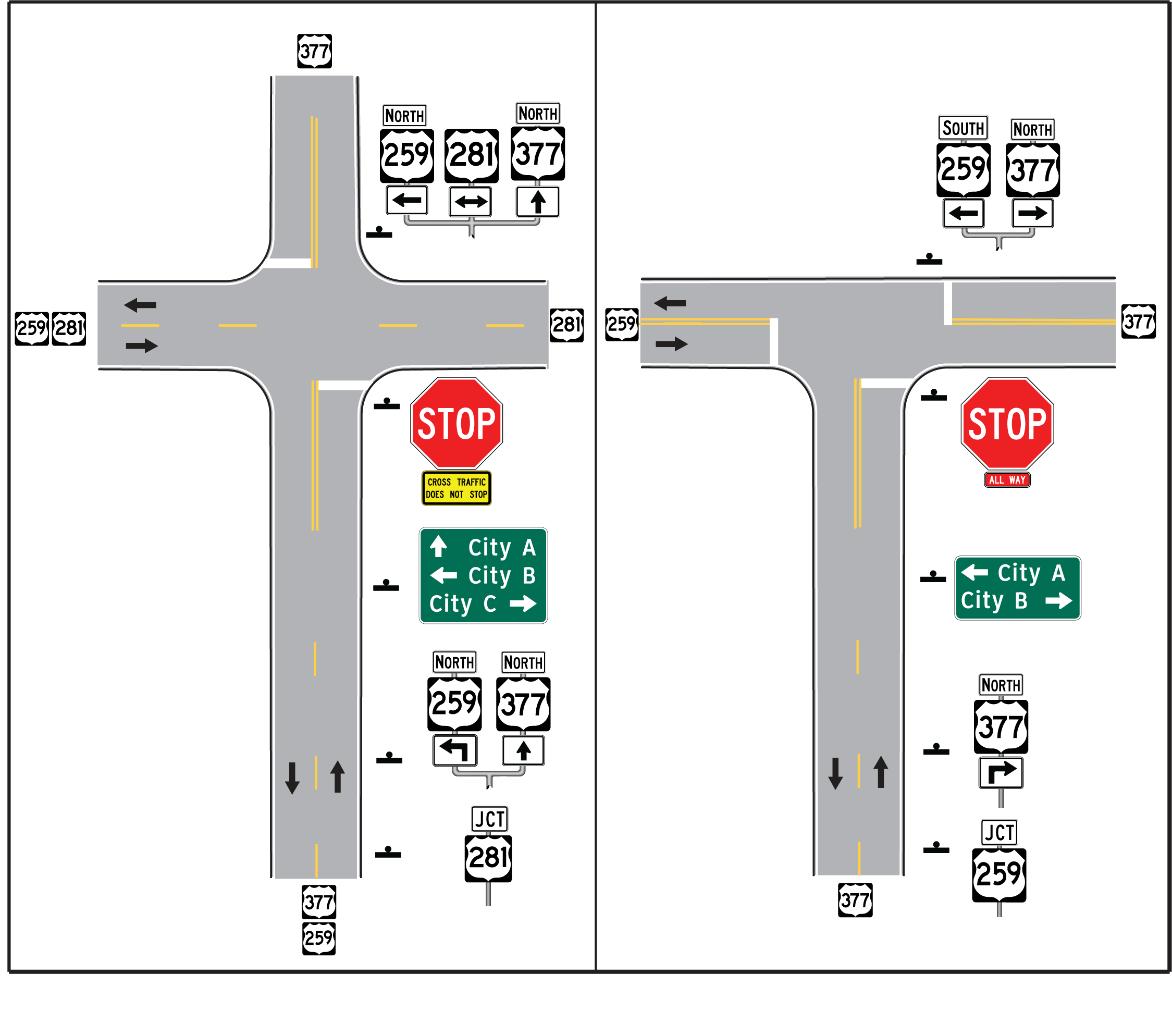
Section 2D.31 of the Texas MUTCD requires an Advance Route Turn Assembly to be used (shall condition) where a turn must be made at an intersection to remain on the indicated route. Figure 3-26 illustrates the two situations where an Advance Route Turn Assembly is required.
Figure 3-26. Required Applications of Advance Route Turn Assembly
Anchor: #i1004420Directional Assembly (Texas MUTCD Section 2D.32)
Purpose: The Directional Assembly is used at an intersection to provide information about travel on one or more intersecting highways.
Components: The following components make up a Directional Assembly:
- Anchor: #QIFLQJKE
- Standard: Route sign and Directional Arrow auxiliary sign. Anchor: #APYJXFHY
- Optional: Cardinal Direction auxiliary sign.
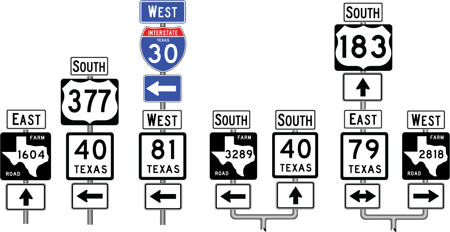
Figure 3-27 illustrates a Directional Assembly.
Figure 3-27. Directional Assembly
The following is a list of preferred locations for Directional Assemblies:
- Anchor: #GFVGVFGP
- Directional Assemblies are located on the near right-hand corner of intersections with no control or signal control. Anchor: #OBFBUHFK
- Directional Assemblies are located on the far right-hand corner of intersections with Stop or Yield control. Anchor: #NDUKSOFO
- At major intersections and at Y or offset intersections, it is desirable to install additional assemblies on the far right-hand or left-hand corner of the intersection to confirm the near-right-hand side assembly. Anchor: #BICJGQOG
- When a near-corner position is not practical, the far right-hand corner is the preferred alternative location. Oversize components may be appropriate to improve legibility. Anchor: #RGYOYRMV
- Where unusual conditions exist, the location of a Directional Assembly is based on engineering judgment with the goal being to provide the best possible combination of view and safety.
Confirming Assembly (Texas MUTCD Section 2D.34)
Purpose: The Confirming Assembly is used beyond an intersection to confirm the highway and direction to the driver after departing the intersection or interchange.
Components: The following components make up a Confirming Assembly:
- Anchor: #DDCMKXQY
- Standard: Cardinal Direction auxiliary sign and Route sign. Anchor: #MQWSKFVW
- Optional: None.
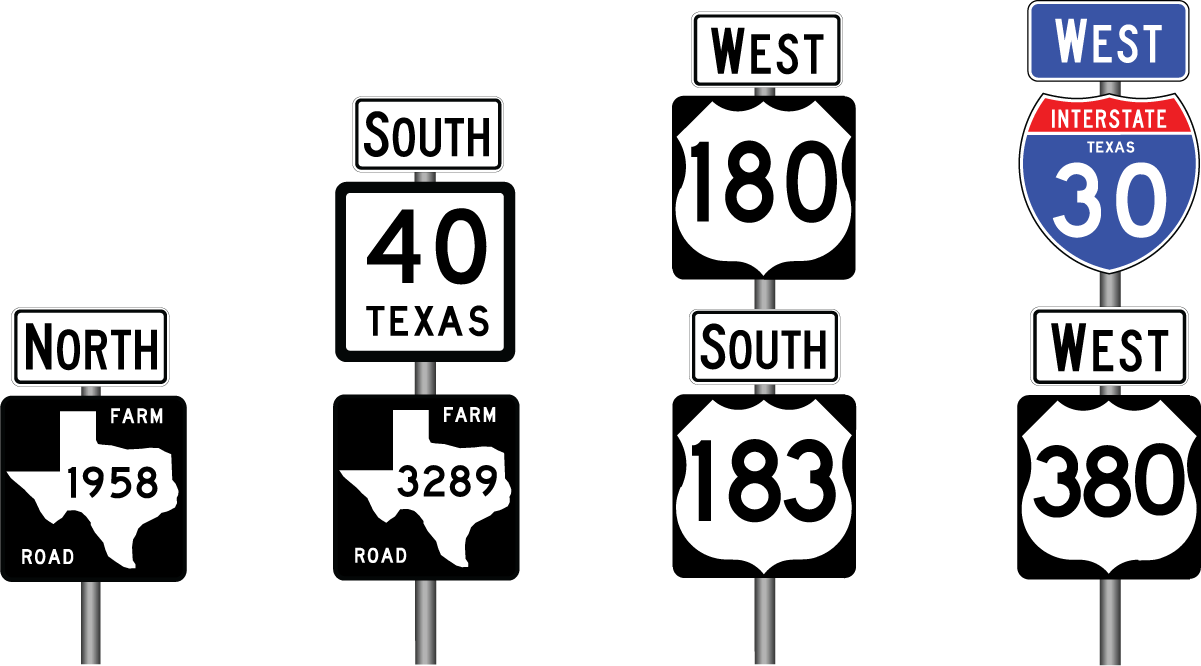
Figure 3-28 illustrates a Confirming Assembly.
Figure 3-28. Confirming Assembly
Anchor: #i1004535Trailblazer Assembly (Texas MUTCD Section 2D.35)
Purpose: The Trailblazer Assembly is used at an intersection to indicate the direction to a highway not located at that intersection. Trailblazer Assemblies may also be used at non-intersection locations to direct drivers to the indicated highway.
Components: The following components make up a Trailblazer Assembly:
- Anchor: #TOKKRMDX
- Standard: TO auxiliary sign, Route sign, Directional Arrow auxiliary sign. Anchor: #OWUEXSTD
- Optional: Cardinal Direction auxiliary sign.
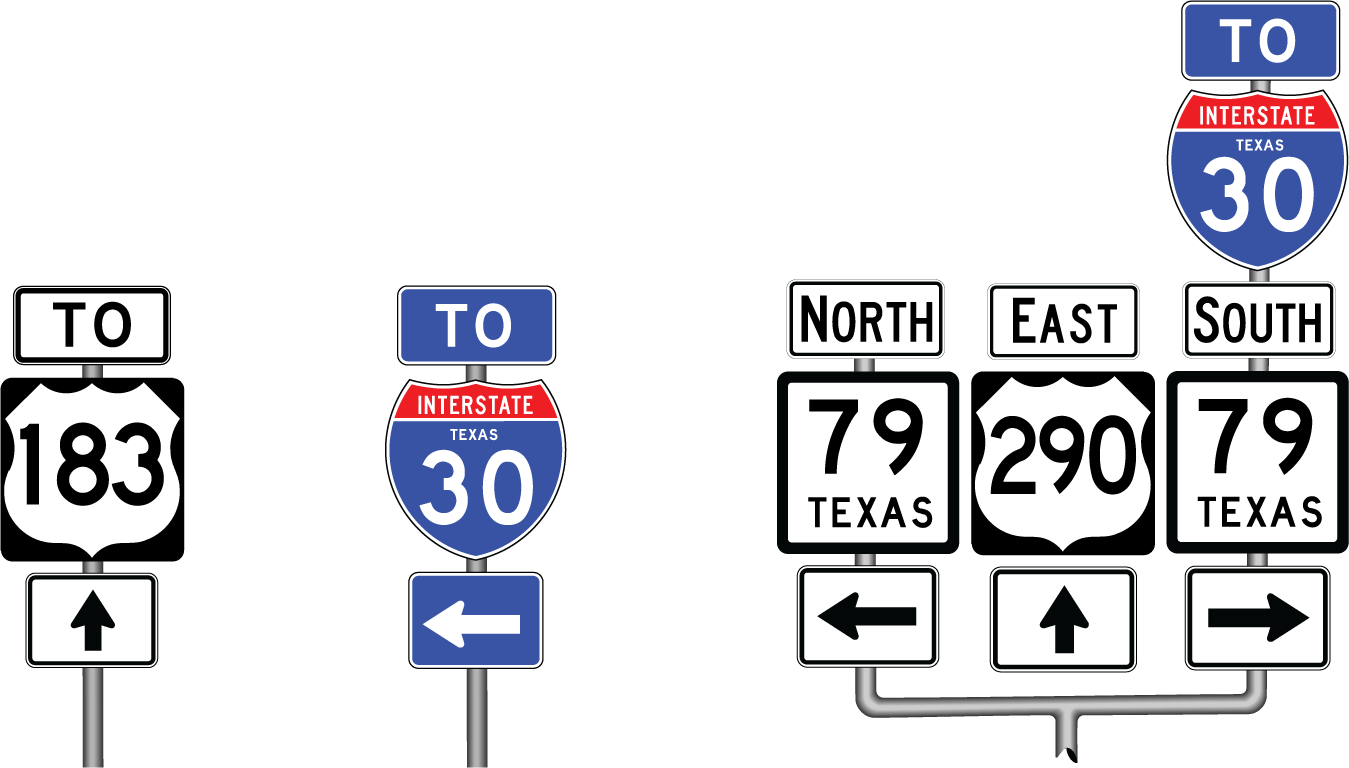
Figure 3-29 illustrates a Trailblazer Assembly.
Figure 3-29. Trailblazer Assembly
A Trailblazer Assembly may be incorporated into the Directional Assembly at an intersection as shown in the assembly on the right side of Figure 3-29.
Anchor: #i1004580Texas Reference Marker Assembly
Purpose: The Texas Reference Marker Assembly provides the tie in the field to the Texas Reference Marker System. These sign installations are provided primarily for TxDOT use in referencing locations on a highway.
Components: The following components make up a Reference Marker installation:
- Anchor: #TOEGQSDV
- Standard: Route sign, Texas Reference marker (front and back of post). Anchor: #TTOWFYKM
- Optional: Cardinal Direction auxiliary sign.
Installation: The following factors describe how the Texas Reference marker should be installed.
- Anchor: #WXAMYWNH
- It is located approximately every 2 miles on a highway. Anchor: #MMGJOBKT
- The preferred installation is:
- Anchor: #CUTXOEXB
- On alternating sides of an undivided highway (4 miles between installations on the same side of the highway). Anchor: #MOMAKODN
- On both sides of a divided highway (2 miles between installations on the same side of the highway). When installed on both sides of a divided highway, one side is the primary installation. The secondary installation must be exactly opposite of the primary installation.
Anchor: #URVRNTXJ - It is installed on both the front and back of the post for all installations. Anchor: #QGBTCPEW
- A reference marker should not be installed on the approach to an intersection (i.e., a reference marker installation should not be located between the intersection and the first sign informing the driver of the intersection, such as the Highway Intersection Ahead or Junction sign). Anchor: #HVSTMTQM
- On concurrent (or overlapping) routes, the reference marker numbers for the higher class highway are used (see ‘Arrangement by Class of Highway’ on page 3-22). If the concurrent highways are of the same class, the reference marker numbers for the lower-numbered route are used.
Figure 3-30 illustrates installation of a Texas Reference Marker.
Figure 3-30. Texas Reference Marker Assembly
