Section 4: Inspection During Application
Anchor: #i1003484Introduction
Inspection of pavement markings during application involves the on-site inspection of the pavement marking during the striping operation. This inspection includes measuring the thickness, width, color, bead dispersion and depth, and nighttime appearance. Inspection during application is important because it allows for problems to be fixed immediately, greatly benefiting all involved. Proper material disposal by the contractor should also be verified.
Anchor: #i1003494Thickness
Inspection of marking thickness is important to ensure that the specified amount of material is being placed on the roadway. Experience has shown that marking thickness is a major factor in the long-term performance of the marking, especially on pavements with surface treatments. Thicker thermoplastic markings on a new surface treatment have been shown to provide better retroreflective performance over time.
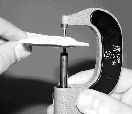
Inspection of pavement marking thickness should be performed in accordance with Test Method Tex-854-B “Determining Thickness of Thermoplastic Stripe.” The recommended method of measuring thermoplastic thickness is by mechanical measurement of a sample with a needlepoint micrometer during the striping operation (Figure 3-1).
Measurements should be made to the top of the binder material, excluding the bead. While calipers have been used in the past, they are no longer considered an approved measurement device for measuring the thickness of pavement markings and should not be used. This is because calipers are unable to measure between the beads, creating artificially high measurements.
Samples should be taken from the striping operation using a metal plate or duct tape. It is absolutely necessary that the duct tape or plate be placed on the pavement surface in a covert manner. This placement prevents the striping contractor from slowing the truck prior to the tape or plate to create an artificially thicker sample.
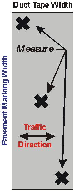
Sampling should occur at maximum 2,000-foot intervals according to Test Method Tex-854-B. A minimum of three measurements should be taken diagonally across each sample as shown in Figure 3-2. All measurements should meet or exceed the thickness specified in the contract. If measurements are less than the thickness specified in the contract, notify the contractor immediately.
Figure 3-1. Needlepoint micrometer measuring thermoplastic sample.
Figure 3-2. Recommended thickness measurement locations.
Anchor: #i1003530Width
Although no test method exists in the TxDOT Manual of Testing Procedures for measuring width, inspection of width should occur. Pavement marking width should be inspected at approximately the same intervals as for marking thickness. Minimum specified widths should be maintained at all times.
Anchor: #i1003542Color
The inspection of daytime pavement marking color is performed in the laboratory according to Test Methods Tex-863-B and Tex-839-B. The CIE chromaticity coordinates of thermoplastic materials must fall into the range specified in DMS-8220. No specification for field measurement of daytime or nighttime pavement marking color is currently in use by TxDOT.
When heat-sensitive materials are applied, such as thermoplastics, marking color should be monitored for changes in color. A greenish-yellow or a dingy-dull white appearance of thermoplastic materials upon application is usually a sign that the materials have been scorched. Another common discoloration problem occurs when the melting kettle is not completely cleaned out when changing material colors. If marking discoloration occurs, stop striping immediately and discard the material.
Anchor: #i1003561Glass Bead Application Properties
During field striping applications, beads are applied either by spraying (pressure drop) or dropping (gravity drop) onto the wet marking material. Retroreflectivity can be controlled to some degree by drop-on bead application procedures.
Important: The two most important field-controlled properties that require on-site inspection are:
- the amount and dispersion of exposed beads across a line
- the depth of embedment of the beads.
Separate discussions of these properties follow.
Table 3-4 summarizes some problems that have been encountered during glass bead application and potential remedies of those problems.
|
Trips |
Tips |
|---|---|
|
Concentration of beads on one side |
|
|
Concentration of beads in middle of line |
|
|
Using excessive amounts of beads |
|
|
Beads are buried in material |
|
|
Beads are partially covered with material (thin-film binders only) |
|
|
Beads are not imbedded sufficiently |
|
|
Surging pattern of beads |
|
|
Excessive amount of beads off the material and on the pavement |
|
Amount and Dispersion of Beads. Inspection of bead coverage across the marking is necessary to assure uniform retroreflectivity across the surface of the marking. In general, the more beads on a surface, the greater the retroreflectivity, although too many beads may cause retroreflectivity to decrease.
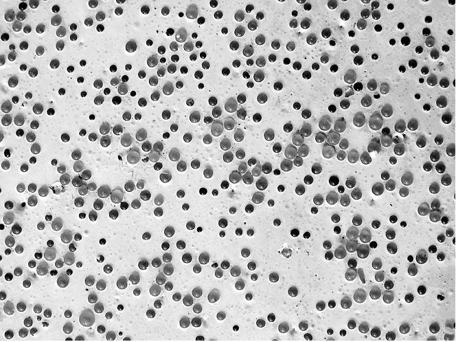
Glass bead dispersion may be visually checked by close-up visual examination or by the sun-over-shoulder method described in Test Method Tex-828-B. Beads should be uniformly applied over the surface of the markings. If they appear otherwise, notify the operator that his bead gun or pump is likely not functioning properly. Figure 3-3 shows an example of a thermoplastic stripe with well-dispersed glass beads.
Figure 3-3. Good glass-bead dispersion for Type III beads in thermoplastic.
When placing a thin-film marking (i.e., water-based paint, epoxy, and other thin-film materials), inspectors should ensure that beads are not “rolling” when dropped onto a marking, which often occurs when the striping truck is traveling faster than 10 mph. When beads roll through a wet thin-film marking material, they become coated with binder, making them useless as retroreflectors.
Bead Embedment Depth. Bead depth can be estimated by close-up visual examination. Beads should be embedded into the pavement marking material at 60 percent of the bead diameter for maximum retroreflective performance. Because the material that is “behind” the bead is the actual image that is reflected back to the driver, it is important that proper embedment depth is achieved. Figure 3-4 shows the effect of bead embedment depth on retroreflectivity.
Figure 3-4. Effect of bead embedment depth on retroreflectivity.
clearly shows that beads not embedded deeply enough will cause the light to be reflected in many directions instead of back to the driver, greatly reducing the retroreflectivity. In addition, beads that are under embedded will be easily worn away after very little traffic wear. Beads that are embedded too deep will still reflect light, but not as much. Therefore, if errors in embedment are made, it is better for the beads to be too deep than too shallow, as can be observed in Figure 3-4.
During the striping operation, if the beads appear to be too high or too low, notify the operator to make adjustments. In the case of hot-applied materials, such as thermoplastic, the material temperature has a major effect on bead embedment. The pressure of the bead applicator also affects bead embedment.
Anchor: #i1003648Nighttime Appearance
Nighttime appearance of pavement markings is critical to roadway navigation at night. The two critical components of nighttime appearance are nighttime color and nighttime brightness. Discussions follow.
Nighttime Color. Depending on the pigments, the nighttime color of pavement markings may appear to be significantly different from the color during the day. This difference is due to the differences in the illumination characteristics between night (headlamps) and day (sunlight) driving. Yellow markings are especially susceptible to having a different color appearance at night. Although not usually a problem in lead-containing thermoplastics, yellow markings containing lead-free pigments have been known to appear whiter at night compared to daytime. Although TxDOT does not currently have a specification for measurement of nighttime color, visual inspection of the color at night provides assistance in future product decisions.
Nighttime Brightness. The brightness of pavement markings at night is influenced by a number of variables, some of which are independent of the pavement marking itself. Factors that are external to the pavement marking include: headlamp aim and intensity, weather conditions (rain, snow, fog), and visual capabilities of the driver. The characteristics of the glass beads are the primary influence in nighttime brightness within the marking itself.
Nighttime brightness of pavement markings can be estimated during the striping operation using one of the following two methods:
- performing the sun-over-shoulder test
- measuring marking retroreflectivity and comparing the values to minimum specifications.
Discussions of each method follow.
Sun-over-Shoulder Test for Nighttime Brightness. The sun-over-shoulder test is described in Test Method Tex-828-B “Determining Functional Characteristics of Pavement Markings.” The highlights of this test method are described in Table 3-5. This method is only to be performed when the sun is 20 to 80 degrees above the horizon. Using this method, if the beads are properly embedded and dispersed, the line will have a vibrant and uniform glow. Figure 3-5 shows an example of the sun-over-shoulder test.
|
Step |
Action |
|---|---|
| 1. |
When the sun is 20 to 80 degrees above the horizon, position yourself so that the sun is behind you. |
| 2. |
View the stripe in front of you along a plane parallel to your shadow. |
| 3 |
Adjust your distance from the stripe to where the shadow of your head touches the stripe area being observed. |
| 4 |
From this position, evaluate the retroreflective qualities of the stripe. |
Figure 3-5. Sun-over-shoulder test from Test Method Tex-828-B.
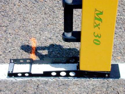
Measuring Marking Retroreflectivity to Determine Nighttime Brightness. Marking retroreflectivity is measured with a portable handheld retroreflectometer and then compared to the values to TxDOT minimum specifications for retroreflectivity of new pavement markings. Figure 3-6 shows an example of a retroreflectometer that is prepared for measurement.
Figure 3-6. Handheld instrument prepared for retroreflectivity measurement.
Results of Nighttime Brightness Measurements. Notify the operator immediately if the markings are not passing the nighttime brightness measures. In some cases, instrument measurements may not provide an accurate measurement of the actual retroreflectivity of the marking. This disparity typically occurs where the surface is not flat (i.e., when the marking is located on a steep crown or joint in the concrete). Care should be taken when selecting a location to take retroreflectivity readings. Whenever possible, retroreflectivity measurements should be made where the pavement surface is flat.
Anchor: #i1003724Material Disposal
Typically, unused materials are carried over to the next striping job. However, situations often arise that require a test spray or a complete flush of the kettle and guns. Contractors often perform test sprays prior to thermoplastic striping to warm up the guns and verify that the guns are spraying properly. In addition, contractors often flush out their kettle and guns when switching to material of a different color or after finishing for the day.
Inspectors should verify that contractors are properly disposing of marking materials when performing test sprays or flushes. Although not a standard requirement, some districts require that contractors collect all excess striping material into a pan instead of spraying on the ground.
Contractors will often capture flushed-out paint material for re-mixing with new material, which is allowed only if detergents are not used. Two-component materials should never be reused once sprayed.
Flushing of the entire truck should not be allowed at the job site for any material. Contractors are also not allowed to dispose of any material into storm sewer drains.
Anchor: #i1003751Solutions to Common Problems Associated with Various Striping Applications
Occasionally during the application of a pavement marking material, problems may be encountered that will cause the marking to have an abnormal appearance and reduce the service life. The following tables in Chapter 2 describe problems that may be observed during the application of various marking materials and corresponding remedies to these problems:
|
For Tips on: |
See: |
|---|---|
|
Thermoplastic Application |
|
|
Paint Applications |
|
|
Epoxy Application |
