Section 2: Freeway Direction Signs (White on Green)
Anchor: #i1002635Introduction
The majority of freeway guide signs are the white-on-green direction signs that road users rely upon to provide most of the navigation information they need. Direction signs can be placed overhead or on the side of the freeway and include the following:
Overhead direction signs include:
- Advance Guide signs
- Exit Direction signs
- Exit Number panels
- Diagrammatic signs
- Interchange Sequence signs
- Pull-Through signs.
Ground-mounted direction signs include:
- Exit Gore signs
- Supplemental Guide signs
- Distance signs.
Overhead Sign Placement
Overhead signs are used when some degree of lane-use control is desired or where space is not available at the roadside. The following table provides sources of information on the placement of overhead signs.
|
For information on… |
See… |
|---|---|
|
Factors justifying the installation of overhead signs |
Texas MUTCD, Section 2A.17 |
|
Vertical clearance of overhead signs |
Texas MUTCD, Section 2A.18 |
|
Design and layout of overhead sign bridge structures |
Traffic Engineering Standard Sheets (OSB & Monotube Series) |
Anchor: #i1002714
Advance Guide Signs
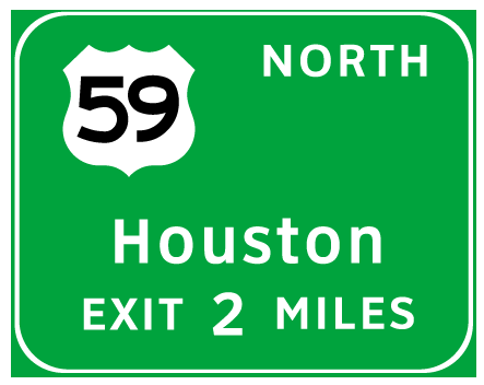
Advance Guide signs (see Figure 3-1 for example) provide advance notice of an upcoming interchange and the distance to the interchange.
Figure 3-1. Advance Guide sign.
Advance Guide signs are addressed in Section 2E.30 of the Texas MUTCD. For design and layout of Advance Guide signs, see Chapter 4, Freeway Guide Sign Design of this manual.
Design and Application. Advance Guide signs must include a destination and a distance to the exit. If appropriate, Advance Guide signs must also include a cardinal direction, Route sign, Exit Number panel, and Exit Only panel.
The distance may be omitted when there is an Exit Only panel and the distance to the exit is less than 1 mile.
The word EXIT should be omitted from the distance portion of the sign legend (i.e., Exit 1 Mile) if an Exit Number panel or an Exit Only panel is used.
If the freeway has numbered exits, an Exit Number panel must be used.
The legend in the Advance Guide sign must have the same format as the legend in the downstream Exit Direction sign, and the content should be consistent with the content of the Exit Direction sign.
Distances shown on Advance Guide signs should be shown as fractions and rounded to the nearest ¼ mile.
Number of Signs. If there is adequate space, an Advance Guide sign must be used for each interchange. Recommendations are as follows:
- For minor interchanges, one Advance Guide sign should be used.
- For intermediate and major interchanges, at least two, and preferably three, Advance Guide signs should be used.
If adequate space is not available, Interchange Sequence signs should be used.
Placement. Typical placements for Advance Guide signs are as follows:
- For minor interchanges, ½ mile to 1 mile.
- For intermediate and major interchanges, 2 miles, 1 mile, and ½ mile.
Exit Direction Signs
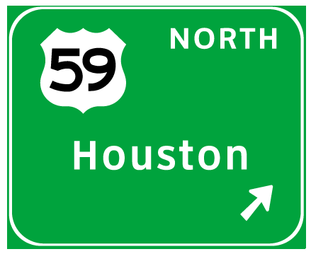
Exit Direction signs (see Figure 3-2 for example) are used to indicate the location of an exit ramp from the freeway.
Figure 3-2. Exit Direction sign.
Exit Direction signs are addressed in Section 2E.33 of the Texas MUTCD. For design and layout of Exit Direction signs, see Chapter 4, Freeway Guide Sign Design of this manual.
Design and Application. The following information covers the design and application of Exit Direction signs:
An Exit Direction sign should be used wherever traffic can exit from a freeway.
Exit Direction signs must include a destination and upward slanting arrow. If appropriate, Exit Direction signs must also include a cardinal direction, Route sign, Exit Number panel, and Exit Only panel.
Where the exit is a lane drop, a new TxDOT policy specifies that the arrow should be in the yellow Exit Only panel (black arrow) instead of a white arrow in the green portion of the sign.
The legend in the Exit Direction sign should have the same format as the legend in the upstream Advance Guide sign, and the content should be consistent with the content of the Advance Guide sign.
If the freeway has numbered exits, an Exit Number panel must be used.
Diagrammatic signs must not be used at the Exit Direction sign location.
Vertical Placement. The Texas MUTCD provides the following guidance concerning the vertical location of Exit Direction signs:
- The signs must be overhead where a through lane is terminated (lane drop).
- The sign should be overhead where there is less than 300 feet from the beginning of the deceleration lane to the theoretical gore.
- For multilane-exit interchanges, the sign should be located over the exiting lane.
Horizontal Placement. The Texas MUTCD provides the following guidance concerning the horizontal location of the Exit Direction sign:
- Ground-mounted Exit Direction signs should be installed at the beginning of the deceleration lane.
- Overhead Exit Direction signs should be installed at the theoretical gore.
Exit Number Panels
The Exit Number panel provides a means of identifying interchanges. In Texas, interchanges on Interstate highways are numbered using milepost marker (reference post) numbers. Exit numbers are not normally used on non-Interstate freeways in Texas. Figure 3-3 illustrates two types of Exit Number panels.
Figure 3-3. Exit Number panels.
Exit Number panels are addressed in Section 2E.28 of the Texas MUTCD and the Standard Highway Sign Designs for Texas.
Design, Application, and Placement. The following information covers the application, design, and placement of Exit Number panels:
The Exit Gore Sign Number panel must contain only the exit number.
The Guide Sign Number panel must contain the word EXIT and the exit number.
The Exit Number panel must be located at the top of the Advance Guide and Exit Direction signs or Exit Gore sign.
The Exit Number panel (for Advance Guide and Exit Direction signs) must be aligned to the side of the exit. The Number panel must be aligned to the right edge for a right-side exit and the left edge for a left-side exit. The Exit Number panel for Exit Gore signs must be centered to the parent sign.
Anchor: #i1002960Diagrammatic Signs
Diagrammatic signs are guide signs that show a graphic view of the exit arrangement in relation to the main highway. Diagrammatic signs are not widely used for freeway signing in Texas, although there are some situations where their use may be advantageous.
Diagrammatic signs are addressed in Section 2E.19 of the Texas MUTCD.
Minimum graphic sizes are listed in Table 2E-2.1 of the Texas MUTCD.
Because diagrammatic signs are not widely used in Texas, designers should contact the Traffic Operations Division before including diagrammatic signs in a project.
Anchor: #i1002985Interchange Sequence Signs
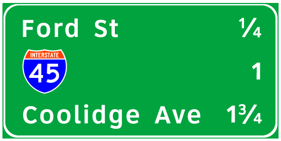
Interchange Sequence signs (see Figure 3-4 for example) are used instead of Advance Guide signs where the spacing between interchanges is less than 800 feet.
Figure 3-4. Interchange Sequence sign.
Interchange Sequence signs are addressed in Section 2E.37 of the Texas MUTCD. For design and layout of Interchange Sequence signs, see Chapter 4, Freeway Guide Sign Design of this manual.
Application and Placement. Interchange Sequence signs should not be used on a single-interchange basis. When used, Interchange Sequence signs should be used over the entire length of a route.
TxDOT uses Interchange Sequence signs in urban areas with populations of 100,000 or greater.
Design. Minimum letter height requirements (as shown in Table 2E-2.1 of the Texas MUTCD) are as follows:
- Interchange name: 13.3 inches for uppercase.
- Numeral: 13.3 inches.
Distances shown on Interchange Sequence signs should be shown as fractions and rounded to the nearest ¼ mile.
Chapter 9, Section 2, of the Signs and Markings Volume of the Traffic Operations Manual provides the following additional guidance concerning the design and layout of Interchange Sequence signs:
- An Interchange Sequence sign should not include more than three exits. Anchor: #i999514
- An Interchange Sequence sign must not include destinations, city names, memorial highway names, periods, arrows, or EXIT ONLY messages.
Pull-Through Signs
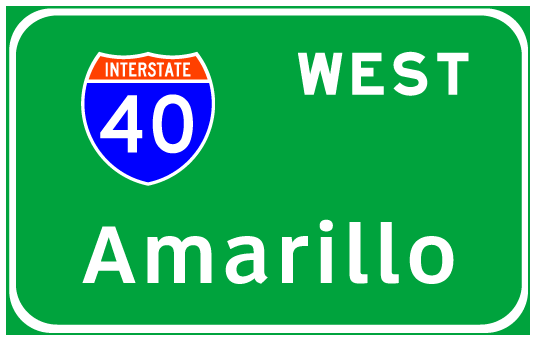
Pull-Through signs (see Figure 3-5 for example) are overhead Lane-Use signs intended for through traffic. Pull-Through signs are addressed in Section 2E.11 of the Texas MUTCD.
Figure 3-5. Pull-Through sign.
Application. Pull-Through signs should only be used to identify the through lanes when it may not be readily evident to the road user which lanes are the through lanes.
Design. Minimum letter height requirements (as shown in Table 2E-2.1 of the Texas MUTCD) are as follows:
|
Destination |
16 inches for uppercase |
|
Cardinal direction |
12 inches |
|
1- or 2-digit shield |
36 inches × 36 inches |
|
3-digit shield |
45 inches × 36 inches |
Pull-Through signs should only include Route signs, cardinal directions, and major destinations (or control city). Down arrows should be used for clarity when the alignment and number of through lanes is not readily evident. When down arrows are used, an arrow should be positioned above each lane to which the Pull-Through sign applies.
Placement. When an overhead sign bridge is provided, a Pull-Through sign should be provided over the appropriate lanes (on same structure as the Exit Direction sign).
Anchor: #i1003110Exit Gore Signs
Exit Gore signs (see Figure 3-6 for examples) are used to indicate the place of departure from the main roadway. Exit Gore signs are addressed in Section 2E.34 of the Texas MUTCD.
Figure 3-6. Exit Gore signs.
Design and Application. The Exit Gore sign must contain the word EXIT and an arrow. If the freeway has numbered exits, an Exit Number panel must be used above the Exit Gore sign. The Exit Number panel must be aligned to the side of the exit.
There are two sizes of Exit Gore signs (see Texas SHSD). The larger size should be used for major and intermediate interchanges. The smaller size may be used for minor interchanges.
Any of several arrow designs may be used on the Exit Gore sign, depending upon the sign size and the alignment of the exiting ramp.
- The straight arrow (A-2 or B-1) should be used for a ramp with a primarily tangent alignment.
- The curved arrow (E-3 or E-3a) may be used for a ramp with curved alignment.
- The circular arrow (E-4 or E-4a) may be used for a loop ramp.
Placement. The Exit Gore sign shall be located in the gore between freeway main lanes and the exit ramp.
Anchor: #i1003167Supplemental Guide Signs
Supplemental Guide signs (see Figure 3-7 for examples) provide information regarding destinations accessible from an interchange, other than places shown on the standard Advance Guide or Exit Direction signs. Supplemental Guide signs are addressed in Section 2E.32 of the Texas MUTCD.
Figure 3-7. Supplemental Guide signs.
Design. Minimum letter and numeral sizes for Supplemental Guide signs (as listed in Table 2E-2.1 of the Texas MUTCD) are as follows:
- Exit number word: 10 inches.
- Exit number numeral and letter: 15 inches.
- Destination: 13.3 inches for uppercase.
- Action message: 10 inches.
The sign should list no more than two destinations.
Destinations should be followed by the interchange number (and suffix), or if interchanges are not numbered, by the legend NEXT RIGHT or SECOND RIGHT or both, as appropriate.
Application. No more than one Supplemental Guide sign should be used on each interchange approach.
Supplemental Guide signs should be installed on an independent guide sign assembly.
Where two or more Advance Guide signs are used, the Supplemental Guide sign should be installed approximately midway between two of the Advance Guide signs. If only one Advance Guide sign is used, the Supplemental Guide sign should follow it by at least 800 ft.
Anchor: #i1003239Distance Signs
Distance signs (see Figure 3-8 for example) indicate the distance to significant destinations. Distance signs are addressed in Section 2E.36 of the Texas MUTCD.
Figure 3-8. Distance sign.
Design. Minimum letter and numeral sizes for Distance signs (as listed in Table 2E-2.1 of the Texas MUTCD) are as follows:
- Destination: 8 inches for uppercase.
- Numeral: 8 inches.
A Distance sign usually contains two or three lines. The maximum number of lines is three.
The top line must identify the name and actual distance to the community or destination (or route number or name if there is no community) associated with the next meaningful interchange.
The bottom line must provide the name and distance to a control city (on interstate highways) or an equivalent city (on non-interstate routes).
Placement. If the space between interchanges permits, Distance signs should be located at the end of a three-sign sequence beginning 500 ft beyond the end of the acceleration lane as follows:
- Route sign: 500 ft beyond the end of the acceleration lane.
- Speed Limit sign: 1,000 ft beyond Route sign.
- Distance sign: 1,000 ft beyond Speed Limit sign.


