Section 3: Utility Installation Review Permit Design Documentation Standards
Anchor: #i1027553General
All design criteria must conform with Title 43, Texas Administrative Code, Chapter 21, Subchapter C. The location and manner in which a utility facility installation, adjustment, or relocation work will be performed within the right of way must be reviewed and approved by the Department. Measures must be taken to preserve the safety and free flow of traffic, the structural integrity of the highway or highway structure, ease of highway maintenance, the appearance of the highway, and the integrity of the utility facility.
All Design Documentation shall be submitted electronically with a Utility permit request and shall fully depict the scope of work to be performed by the Utility Installation Owner.
For Broadband Installations, the Utility Installation Owner shall indicate the design of the Node Support Pole, the Network Node, and any other Attachments (such as fiber demarcations, battery backup, and power meters) in the Design Documentation. Design Documentation shall include any handholes, manholes, pedestals, demarcation enclosures, splice cases, and ducts surrounding the installation and illustrate how the Node Transport Facility and power will interconnect with the Network Node.
Design Documentation shall be specific to the design with no handwritten or superimposed annotations other than the Professional Engineer's signature and stamp where required. Design Documentation containing strictly generic standards will not be accepted. Design Documentation shall be original plotted digital renderings created with computer-aided design software and presented in PDF file format. No individual document may be larger than 5 MB in size. Scanned Design Documentation or Design Documentation of poor visual quality (as determined by the Department reviewer) may not be accepted.
Anchor: #VXPNAWSAPaper Size
All Design Documentation shall be legible when printed according to the ANSI B standard for 11 inches x 17 inches. Drawings may be submitted in a larger, ANSI D format (i.e., 22 inches x 34 inches) but must contain an accurate alternate scale when printed at 11 inches x 17 inches. Architectural sizes (i.e., ANSI A, and ANSI C) are not acceptable formats.
Anchor: #i1027688Abbreviations
All annotations, callouts, notes, and descriptive text shall be in plain language. If abbreviations are used to promote clarity in the Design Documentation, the applicant shall follow the TxDOT Style Guide for Construction and Maintenance Specifications.
Anchor: #i1027716Line Weights and Annotations
Descriptions of existing above-ground features on Plan View and Profile View sheets shall have a consistent line weight. Descriptions of existing below-ground utilities and features shall have a consistent line weight that is lighter than existing above-ground features. All features and components of the proposed installation-as opposed to existing conditions-shall have a consistent, heavier line weight than existing above-ground features. All annotations for the proposed installation shall be bolded and noticeably heavier than other annotations on the Plan and Profile sheets.
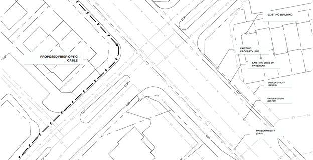
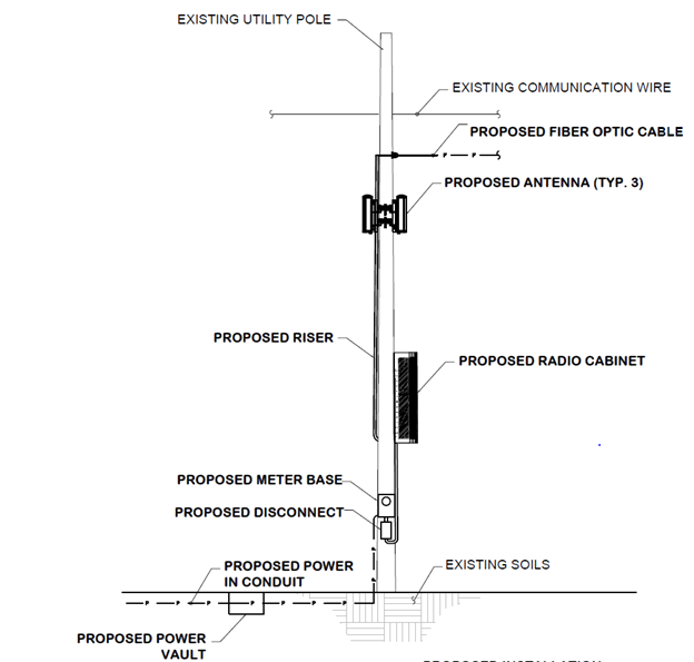
A Plan sheet example with suitable line weights and annotations is shown in Figure B-1. A sample Profile sheet with suitable line weights and annotations is shown in Figure B-2.
Figure B-1. Sample Plan Sheet with Suitable Line Weights and Annotation. Note: Annotations for travel lanes, road names, numbers, clear zone, and ROW were omitted for clarity.
Figure B-2. Sample Profile Sheet with Suitable Line Weights and Annotation (South View)
Anchor: #i1027744Required Sheets and Information
Design Documentation shall include, at a minimum, the following sheets for all types of applications except for Broadband Installation removal:
- Anchor: #FQAONNKW
- Title Sheet Anchor: #JFYIMYUW
- Plan Anchor: #SFJLGGJA
- Profile Anchor: #HTQHJEEI
- Equipment Anchor: #RLASMDTC
- Traffic Control Plan Anchor: #MQGUKBSH
- Standards (optional)
Applications to remove a Broadband Installation shall include:
- Anchor: #LFAHJYTP
- A title sheet Anchor: #BQBEPYWQ
- A list of items that will be removed Anchor: #OMPOSDNG
- Traffic Control Plans, and Anchor: #DFBEUOSX
- A description of the proposed restoration
Title Sheet Requirements
The title sheet shall include the following items:
- Anchor: #IOPVSBWN
- State road (name and number) Anchor: #DGYDQXSJ
- TxDOT District (name and number) Anchor: #SYCHCQMV
- Network Provider's site name and/or identifier number (e.g., “Abilene - North,” “TX3449859”) Anchor: #QMNAQPMK
- Full address of proposed Broadband Installation location (if none available, use the closest address to assist the reviewer in finding the site) Anchor: #BKCHKOFY
- Historic or Design District name, if applicable Anchor: #NWUQKNNL
- Latitude and longitude are expressed in degree/decimal format (e.g., XX.XXXXXX) to the NAD83 standard and accurate to ±1 meter. Anchor: #URARORNW
- Email and phone number for the applicant's engineer Anchor: #CRYXBDXB
- Email and phone number for the applicant's single point of contact Anchor: #ULIRGFGM
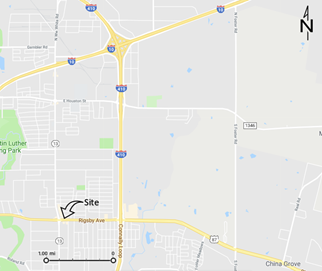
- 5-square-mile map of the area for orientation purposes (see Figure B-3)
Figure B-3. Sample 5-Square-Mile Area Map
- Anchor: #NPATWQII
- A list of Applicable Codes and Applicable Engineering Standards (most recent version) with which the application complies Anchor: #ARTAEDKH
- Sheet index (table of contents) listing only submitted sheets Anchor: #ISPDAIWV
- Seal and signature from a State of Texas-certified Professional Engineer (P.E.) Anchor: #LPNQIWCI
- Professional Engineer's statement with the following signature line placed in the lower right-hand quadrant of the title page:
Figure B-4. Sample of Professional Engineer’s Statement
Anchor: #i1027821Requirements for Plan Sheets
The Plan sheets shall accurately depict existing features that apply, such as:
- Anchor: #KILRTYND
- State roads and interstates (name and number) Anchor: #RHQWTUFN
- Municipal roads (name) Anchor: #OKLKXEMD
- Toll roads (name) Anchor: #CTEECYYF
- Private raods Anchor: #TTYSPNCX
- Travel lanes with traffic direction arrows Anchor: #UGWLTXXD
- Clear zones Anchor: #CEDSWNNJ
- Distance from proposed installation to the right of way line Anchor: #AWPLRBFC
- Right of way width Anchor: #QBDUPXXE
- Department Rights-of-Way and other rights-of-way and property lines Anchor: #KHIMCMUU
- Sidewalks and accessibility ramps Anchor: #WXQLNRRR
- Bike trails/lanes/paths Anchor: #XRYPOHTG
- All existing visible features, street furniture, and structures within the Department Rights-of-Way Anchor: #DFDGOCFW
- Property addresses for parcels abutting the Department Rights-of-Way Anchor: #OHUDGPKC
- Area zoning boundaries and an indication of the zone type, if any (e.g., residential, mixed-use, commercial, industrial) Anchor: #VLJSPIMS
- Premises outlines with address numbers, if applicable Anchor: #FYSHDLPM
- Existing underground utilities if available from the municipal GIS source(s) Anchor: #HWBXPRPD
- Visible underground utility appurtenances (e.g., valves, fire hydrants) Anchor: #QILJULBP
- Annotation to identify the surface type (e.g., pavement, grass, bituminous) Anchor: #BPJWIAIV
- Hydrology/flood plains Anchor: #AGMVMYEE
- Stormwater management and culverts Anchor: #NAFLSFPD
- North arrow indication Anchor: #JWXKXKGO
- Recorded easements Anchor: #RSVLVNUN
- Limits/boundary of construction Anchor: #BFRVKCII
- Notes to identify the method of construction (if not explained on a standards sheet) Anchor: #FPBBJJSX
- Reference to any applicable detail illustrations on the plan sheet or a separate standards sheet Anchor: #XRSIMDPL
- Any structure proposed to be installed or replaced Anchor: #TSCXOXEW
- A color photo of the proposed Broadband Installation location (with approximate placement identified) taken during a field survey conducted within 60 days of the date of the application submittal; internet street-view photos are not acceptable, and the size of the photo shall be no less than 3 x 4 inches when printed on an 11 x 17-inch sheet
Plan sheets may have aerial imagery as the base layer. The Applicant's Professional Engineer shall confirm that the aerial imagery is suitable to depict current conditions as related to the application. If a plan sheet with aerial imagery is used, an additional plan sheet of the same perspective, orientation, scale, and detail will be required without the imagery.
Plan sheets shall include the dimensions of all setbacks, offsets, and road widths related to the proposed Broadband Installation. Dimensioning should include but not be limited to:
- Anchor: #YGTAXYLY
- Road and Department Right-of-Way widths Anchor: #XSGELJKR
- Distance from existing and proposed underground facilities to the Department Right-of-Way and edge of pavement Anchor: #QSEQDIXJ
- Distance from hydrology and flood plains to proposed facilities Anchor: #RRXTFLOP
- Clear zone width and offset to proposed facilities Anchor: #CSEYYUGI
- Widths of sidewalks, accessibility ramps, bike trails, bike lanes, and bike paths Anchor: #OIJOWPSO
- Setback to premises Anchor: #ABODQMPU
- Length of Node Transport Facilities
Plan sheet features shall be drawn to scale except for symbols. Symbols are only to be used to preserve clarity (i.e., an existing 8-inch water line does not need to be drawn to scale). The main plan sheet scale must be in the range from 1:30 (inch: foot) to 1:50. Detailed illustrations can be added to show greater clarity using a larger scale (e.g., 1:10 or 1:5).
Anchor: #i1027849Profile Sheet Requirements
A Profile Sheet shall accurately depict the following items:
- Anchor: #BUQLBJMI
- View direction (facing) Anchor: #KPALFGDC
- The entire dimension of the Pole or Service Structure (new/proposed/existing) Anchor: #CMYPWHKD
- Existing structure view, if the proposed Broadband Installation will replace or be attached to an existing structure Anchor: #VODIAPKU
- Proposed structure view, or two different adjoining views (e.g., north and west) if it is a new structure Anchor: #DVFUCXJB
- All attached Network Node equipment (e.g., antenna, Network Node, ancillary equipment) Anchor: #ALJBMKYP
- Node Transport Facility location and depth (if part of the application) Anchor: #GVFKUHAS
- Foundation view or reference to Typical sheet for proposed foundations Anchor: #XMMXFMRR
- Buried pole depth for new or replaced Pole or Service Structure without foundation Anchor: #OWVDGPOI
- Proposed hand boxes, vaults, and hand holes Anchor: #EUTYUWAM
- Proposed underground conduits (within 10' of the network support structure) Anchor: #WXFNWRID
- Grounding detail or reference to Typical page Anchor: #CAJBDHTL
- Proposed ground-based enclosure Anchor: #DONVBNCA
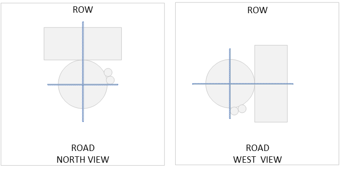
- Node Position Key to Department Right-of-Way and road alignment for each Profile View (see Figure B-5). This detail does not have to be to scale but must show alignment on a quadrant and reference the street and the ROW perspectives. Anchor: #YGALMCXU
- Roadway features, including driveways, ramps, and sidewalks, to verify Pole location will not interfere with proposed Improvements Anchor: #JQMHSJTJ
- Minimum depth of cover for proposed power and communications conduit Anchor: #VISSCTHQ
- Offset from Department Right-of-Way line to power
All the following items shall be dimensioned:
- Anchor: #QOXPWEQP
- Antenna height above Pole or Service Structure Anchor: #PLHJACSQ
- Pole or Service Structure dimension at the base Anchor: #EXCXYYYI
- Distance from Department Right-of-Way line Anchor: #KNUMEJJD
- Antenna and cabinet offset from Pole or Service Structure Anchor: #XKAYSFMP
- Overall height of the Pole or Service Structure above grade Anchor: #RHCJEPJQ
- The vertical clearance of any adjacent overhanging roadway Anchor: #VKJPRXLS
- Ground-based enclosures and height above grade Anchor: #VYWBETIC
- Pole-mounted or Service Structure-mounted enclosures and height above grade
Figure B-5. Node Position Key
Anchor: #i1027877Equipment Sheet Requirements
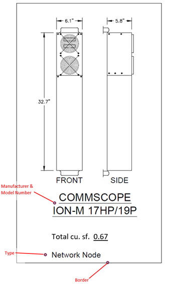
Equipment sheets are specialized Typical Detail sheets that tabulate Cubic Volume for a Broadband Installation. An equipment sheet shall accurately include each of the following that applies:
- Anchor: #PJOGIHDO
- Plan View and Profile View, or multiple Profile Views, or combined Plan View and Profile View (isometric) of any visible component with a measurement greater than 6" Anchor: #MOYUCENQ
- List of external components separately in Typical Detail Anchor: #XRCVEVGJ
- Length, width, and depth in inches or feet and inches for any length greater than 10' Anchor: #IILILEKR
- Manufacturer and model number Anchor: #RKLUSDMN
- Total cubic feet
Each component shall be identified as an antenna, a Network Node, or ancillary equipment. Each Typical Detail on the equipment sheet shall be numbered and labeled to reference the Typical sheet. The use of borders around details is required. See Figure B-6.
Figure B-6. Sample Typical Detail (Network Node)
In addition to the individual component Typical Detail, each equipment sheet shall include a separate note box that identifies the total Broadband Installation volume, in cubic feet, as shown in Figure B-7. The total cubic feet note shall be in bold type, located in the lower right-hand quadrant of the equipment sheet.
Figure B-7. Sample “Total Cubic Feet” Note
Linework and annotations shall be drafted using computer-aided design software. Scanned or cropped images are not acceptable. Equipment shall be drawn to the scale in the Plan View and Profile View sheets.
Anchor: #i1027905Typical Sheet Requirements
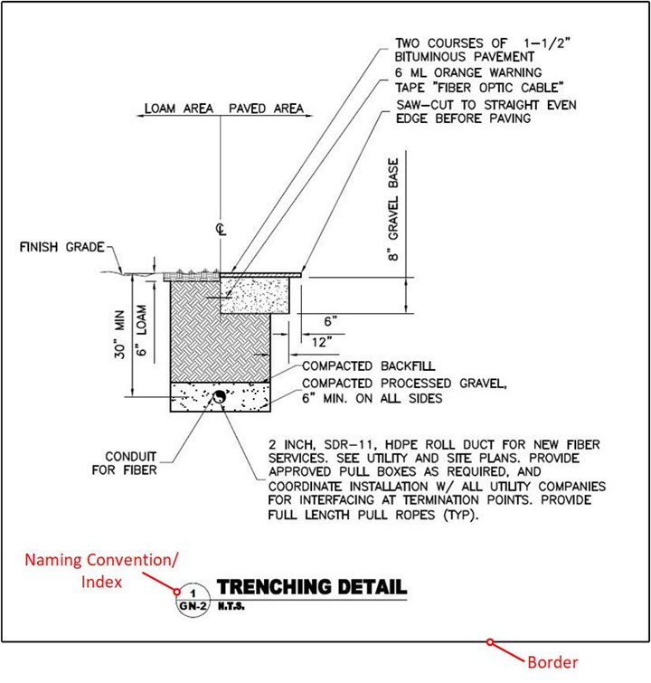
A sheet of Typical Details can be part of the Design Documentation. Only one Typical sheet shall be included per Design Documentation, and each Typical Sheet shall contain no more than eight individual details or illustrations to depict the scope of work related to the plan and profile sheets. Each Typical Detail shall be numbered and labeled to reference the Typical sheet and specific individual details. The use of borders around Typical Details is required (see Figure B-8). Only Typical Details referenced in the Plan or Profile sheets shall be included on the Typical sheet. Examples of Typical Details include:
- Anchor: #BBOIQPNM
- Antenna mounting Anchor: #FKSWCBSX
- Cabinet mounting Anchor: #QBADHLTD
- Break-away fabrication Anchor: #EHRBDRUT
- Concealment Anchor: #WHTFPIMJ
- Concrete pad Anchor: #HNKVVEWO
- Foundation Anchor: #XEOQMGHU
- Hand box / vault / hand hole Anchor: #OQWIKDFQ
- Riser Anchor: #JLMERRUG
- Trench / conduit
Figure B-8. Typical Detail
Anchor: #i1027933Documentation of Demarcation
The Department understands that different Installation owner, and different applications by an Installation Owner may take different business approaches. In some cases, the Installation Owner may propose to build and own the Node Transport Facility. In others, it may build and own the Network Node and another entity may build and own the Node Transport Facility.
The application shall indicate the demarcation between the Node Transport Facility and the Broadband Installation.
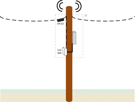
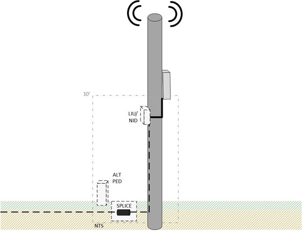
If Network Node equipment is to be located on the Pole or Service Structure itself or the ground in close proximity to the Pole or Service Structure, the handoff from the Node Transport Facility to the Broadband Installation is the demarcation point. The following figures illustrate physical demarcations between the Node Transport Facility and the Network Node at a line interface unit (LIU) also known as the network interface device (NID).
Figure B-9 illustrates a typical scenario in which the Node Transport Facility (dotted line) is delivered aerially. The LIU/NID shown is located on the Pole (it could also be in a nearby handhole if the cabinet is on the ground). The Node Transport Facility provider provides transport from a splice point and drops the line to the NID.
Figure B-9. Example Aerial Node Transport Facility/Network Node Equipment Demarcation Point
Figure B-10 illustrates a typical scenario in which the Node Transport Facility (dotted line) is delivered underground. The Node Transport Facility provider typically builds a handhole containing the transport cable for the Network Node connection. It is recommended that the handhole be located within 10' of the Pole. The demarcation point is where the Node Transport Facility connects to the Broadband Installation.
Figure B-10. Example Underground Node Transport Facility/Network Node Demarcation Point
A Node Transport Facility may be delivered wirelessly as well. In that case, a backhaul antenna may be installed on the Pole or Service Structure, and the LIU/NID would contain the RF equipment used to provide backhaul to the Network Node.
