Section 5: Destructive Evaluation of Pavement Structural Properties
Anchor: #i10051065.1 Introduction
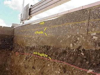
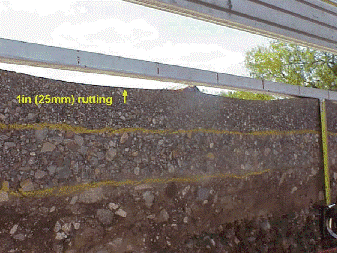
Trenching, coring, and augering have been used in forensic and routine pavement evaluation to determine the source of the problematic layer or layers and acquire materials for further laboratory testing. For example, a section of US 281 had severe rutting, and the district expressed a need to determine the source of the rutting. Although FWD and GPR tests were performed, evaluation of the data could not differentiate from which layer(s) the rutting came. Trenching provides a viable option. Figure 4-16 illustrates the pavement section profiles on US 281. Chalk and stringlines were used to differentiate pavement layers, as shown in Figure 4-16 and Figure 4-17. By exposing the pavement layers, the rutting was found to be restricted to the surface HMA layer.
Figure 4-16. Trench sidewalls showing the pavement layer profile.
Figure 4-17. Trench sidewalls showing severe rutting.
Anchor: #i10051345.2 Trenching Procedure
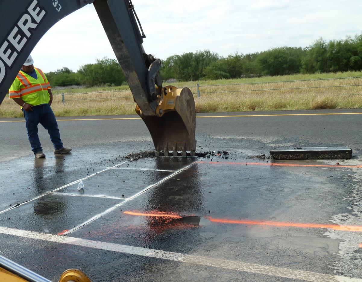
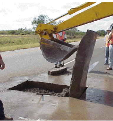
A trenching procedure has been developed to run tests and collect samples while minimizing disturbance to the base material. The saw cut pattern is shown in Figure 4-18. The size of each trench is 3 ft. × 12 ft. Each saw cut is deep enough to penetrate all the way through the HMA layer(s). A strip about 6 in. wide is cut and removed using hand tools from one end of the trench, as shown in Figure 4-19. This creates a slot for the backhoe to reach into and lift the HMA block without major disturbance to the base layer as shown in Figure 4-20. A saw cut is also made across the center of the trench so the HMA blocks can be removed without breaking.
Figure 4-18. Saw cuts for trenching.
Figure 4-19. Removing hot-mix asphalt (HMA) block with backhoe.
Figure 4-20. Flipping hot-mix asphalt (HMA) block out with backhoe.
After the HMA layer is removed and samples are collected, tests can be run and samples collected on the base layer.
The backhoe then digs out the base layer and a few inches of subgrade. Soils and base materials are bagged and taken for further laboratory evaluation, if needed. One of the transverse trench walls (at base and subgrade levels) is then smoothed using shovels, chisels, and brooms. Once a clean trench wall is achieved, the HMA layers are highlighted with chalk, and the base/subgrade layers are highlighted with string lines held with small nails. The thickness of each layer is then measured at regular intervals to determine its contribution to rutting.
Anchor: #i10051815.3 Coring Procedure
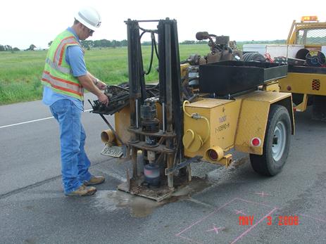
To extract a core sample, the coring rig is placed at the desired location and the barrel-cooling water is turned on, as show in Figure 4-21. Note that dry ice placed in a modified 5-gal. bucket can be used to cool the core barrel if samples at in situ moisture content are desired. This is particularly advisable if any of the HMA layers to be cored are suspected of being stripping-susceptible since a wet-coring process may severely damage these layers in the coring process.
Figure 4-21. Coring using a water-cooled barrel.
The barrel is spun at about 500 rpm and gradually lowered through the asphalt layer. If the base is stabilized, the operator may want to cut through it as well to obtain an intact sample.
After the barrel has cut to the desired depth, it is retracted while still spinning. Then the core barrel is stopped and the location of the core is observed. If the core has twisted off and is now lodged in the barrel, the barrel is struck lightly with a mallet to loosen the core. If the core is still in its original position, metal shims (or screwdrivers) are used to rock the core back and forth until it breaks free from the base or subgrade. Then the core can be lifted out with bent welding rods or loops of thin wire.
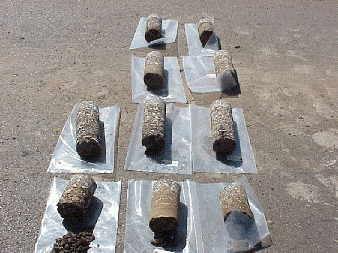
Normally, the core diameter is either 4 in. or 6 in.; 6-in. cores are needed if further laboratory evaluation using Hamburg or the Overlay tester is desired. Figure 4-22 shows the extracted core samples with a 4-in. diameter.
Figure 4-22. Extracted core samples.
Anchor: #i10052245.4 Augering
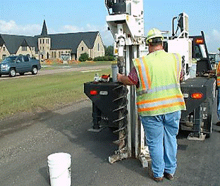
Retrieving samples using an 8- to 12-in. continuous flight auger is useful for determining existing layer thicknesses and for acquiring disturbed samples of all layer materials without resorting to trenching. This sampling technique can be particularly applicable for acquiring materials to determine the type and quantity of stabilizers for full-depth reclamation projects since the consistency of the retrieved materials is similar to those processed through a pavement reclaimer. Figure 4-23 shows a drilling rig with an auger bit attached.
Figure 4-23. Augering a pavement for material samples.
Anchor: #i10052435.5 Shelby Tube
Shelby tube samples have been used to determine the in situ density, moisture content, plasticity index (PI), potential vertical rise (PVR), sulfate content, optimum soil stabilizer, and modulus of the subgrade soil. Samples acquired through this procedure are often termed “undisturbed.”
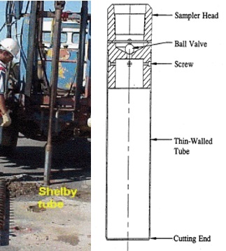
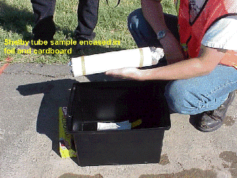
The Shelby tube is a sharpened pipe that is pushed into soil by a hydraulic ram on a truck-mounted boom. These tubes are too fragile to be driven thorough any layer other than unbound fine grained soils. An auger can be used to remove the HMA and base layers, allowing collection of Shelby tube samples without introducing water in the process. After the HMA and base layers are removed, the Shelby tube is positioned on the subgrade and pushed roughly 2 ft. (0.6 m) into the soil, as shown in Figure 4-24. The pipe is then pulled out and placed on a rack. A hydraulic ram then pushes the soil out of the pipe in (hopefully) one cylindrical piece. Aluminum foil and cardboard tubes are used to protect the Shelby tube samples, as shown in Figure 4-25. The tube is labeled with information, including the location, orientation, and depth of the sample.
If deeper samples are desired, the Shelby tube can be extended and pushed into the bottom of the same hole. That sample is then labeled as coming from a lower depth at the same location as the first. In this way, several samples can be collected at any location, then pieced together later for a complete soil profile.
Figure 4-24. Extracting subgrade samples with Shelby tube.
Figure 4-25. Aluminum foil/cardboard tube to protect Shelby tube samples.
