Section 5: Pavement Detours and Pavement Widening
Anchor: #i10417695.1 Pavement Detours
Detours are pavements onto which traffic is temporarily diverted until a permanent (new construction, reconstruction, etc.) structure is provided to carry the traffic over the time frame of a conventional performance period.
Detours can generally be placed into two categories. The first category is the diversion of traffic onto an existing road or roads that parallel or skirt the location of the permanent facility to allow traffic around the construction site. Based on the engineer’s evaluation, the existing road(s):
- Anchor: #EIHUNSWQ
- may be used “as is” if little detrimental effect caused by the additional traffic loading is anticipated, Anchor: #NHGXVJIO
- may need structural upgrading prior to opening of the detour, or Anchor: #XDWCQELT
- may need rehabilitation once the detour is removed.
The second category entails the construction of a temporary facility, usually parallel to and in the general right-of-way of the permanent facility. This type of detour is usually removed when no longer needed or may become integrated into the permanent structure.
Estimating traffic loading over the time frame for a detour is complicated, especially when multiple highway sections are involved. Traffic data for detours can be specifically requested from TPP. For typical detours, the traffic data requested for the parent project will suffice when used in conjunction with the following detour design procedures.
NOTE: The temporary nature of the detour is not a license for ignoring other basic considerations, such as drainage, underlying/edge support, and quality workmanship. These points should be emphasized during the pre-construction conference and actively monitored by inspectors in the field.
5.1.1 Structural Design of Detours
The falling weight deflectometer (FWD) shall be used to evaluate the adequacy of any existing structure (e.g., shoulders or bypass routes) to carry detour traffic.
FPS 21 and the Modified Texas Triaxial Class (TTC) design procedure (as a standalone design option) are the primary analytical methods for detour design. As with all FPS designs, a check using the modified TTC check procedure is required; an allowable alternate version of the standard TTC procedure is described later in this section. If the detour incorporates existing roads/highways, traffic load estimates must include traffic from both sources. Districts may employ proven design strategies for detours and can develop catalog designs based on traffic levels and subgrade support.
When using FPS 21, traffic loading must be entered as the 20-yr. cumulative ESALs. It is only the analysis period that is adjusted to reflect the expected duration of the detour. Set the analysis period and time to first overlay to one or two years. The version of the modified TTC check most commonly used (as in the post-design check built into FPS) assumes a design life of 20 yr. For detours expected to last less than 2 yr., an alternate version of the modified TTC check may be considered – a version sometimes used for evaluating load-zoned highways where the design life is considered to be no more than 10 yr.
In the alternate version, the allowable wheel load scale is essentially doubled, allowing for reduced cover over the standard procedure. The easiest way to perform this alternate version of the modified TTC check is to simply divide the ATHWLD reported from TPP by 2 on the Traffic Analysis for Highway Design report, and enter this wheel load value into the appropriate field of the FPS 21 Modified Texas Triaxial Design check. Depending on the priority of maintaining uninterrupted traffic flow, the tandem axle multiplier can further reduce the overall thickness requirement when set to less than 50%. (NOTE: The tandem axle multiplier is employed when the reported percent tandem axles in the ATHWLD is 50% or greater.) If this alternative option is used, an additional mechanistic check is highly recommended to double check fatigue and rut life.
When using the Mechanistic Check option in FPS 21 to evaluate detour sufficiency in fatigue cracking and subgrade failure (rutting), the routine will estimate the passes to failure in both these modes of a standard 18-kip axle and compare that against the cumulative 18-kip axles in the first performance period of the FPS design. A “check result” message will appear indicating whether the design passes or fails. However, the FPS-calculated performance period is often much longer than the intended detour life; therefore, estimating the cumulative ESALs to the end of the projected detour life may be desirable. One procedure the designer can use to estimate cumulative ESALs over this short detour life is by calculating ESALs in “TRAFFIC6.xls” (refer to MNT, Engineering Applications, to download the spreadsheet) or similar estimating routine, then compare this value against the predicted crack and rut life numbers generated in the FPS Mechanistic Design Check. Refer to the User’s Manual for more details on using the FPS Mechanistic Check feature.
5.1.2 Material and Construction Considerations for Detour Structures
Once a structural design is generated by using any of the cited procedures, other considerations must be made to ensure adequate performance over the expected life of the detour structure. Among these are:
- Anchor: #IUGPSCWF
- adequate pavement width to ensure wheel loads do not encroach upon the pavement edge where lack of lateral support may result in shear failures at the edge; Anchor: #XQBNCMPY
- properly prepared subgrade (including investigation into soil properties). If there are no time constraints for the construction of the detour, stabilization should be considered for low to moderate strength, moisture-susceptible subgrades. Alternately, a geogrid can be used as long as some separation (e.g., thin granular layer) from a proposed HMA lift is planned. The stabilized subgrade will provide a stable construction platform and will help reduce the total thickness of the pavement structure for the detour; Anchor: #UVUAYBAO
- placing 4 in. of flexible base prior to placing any full-depth hot-mix structure if it is not feasible to stabilize the subgrade. The 4 in. of flexible base will help reduce the total thickness of the pavement structure and provide an improved platform to compact the bottom HMA lift against. Improved density in the HMA will increase fatigue life and moisture resistance; Anchor: #YGRQGQBC
- adequate drainage by ensuring proper cross slope, ditch lines, and prevention of ponding; Anchor: #EHEGRMKA
- properly compacted pavement lifts including the HMA surfacing; and Anchor: #RFLBXVXJ
- sufficient HMA density at mat joints and full bonding between HMA lifts.
Proof rolling should be conducted prior to applying surfacing to ensure adequate sheer strength in the unbound layers. Consider the more stringent requirements in the applicable specifications to ensure quality workmanship is used, especially where traffic volumes and level of loading are high.
When the detour structure is no longer needed, mill and recycle pavement layers used in the detour within the parent project to reduce costs.
Anchor: #i10419445.2 Pavement Widening
Widening is conducted to increase the flow capacity of the highway or to improve safety aspects, such as the inclusion of shoulders, turning bays, etc. Consideration shall always be given to maintaining the original cross section for the widened portion. This serves two purposes:
- Anchor: #XCXXDGSK
- it maintains uniformity in the section which facilitates future evaluation and rehabilitation options for the section as a whole, and Anchor: #JDKJXOYS
- it maintains subsurface drainage patterns which are essential to preventing trapped moisture.
Exceptions to this philosophy are generally related to poor performance in the existing section or the desire to expedite construction of the widened section to minimize interference with traffic.
Where traffic control can be facilitated, reworking/widening [add-rock if needed] of the pavement section full-width yielding an upgraded, uniform full-width section can often be obtained for a nominal additional cost over more problematic [poor performing] "scab-on" techniques. Consideration of this technique may be most appropriate for narrower or shoulder widening jobs.
In addition to cross section considerations, full lane-width widening will entail a full-depth joint that is unavoidably a weakened interface in the structure. Compaction against the vertical plane of the old structure will be more difficult to achieve than with full-width construction. Placement of this joint as far from the wheel path as possible will improve performance. Also, applying a final HMA overlay across the entire section with the overlay joint offset by 6-12 in. from the underlying vertical interface will improve the impermeability of the interface over the short term.
The underlying vertical interface at the widening will usually cause reflective cracking through to the surface. An aggressive crack sealing program will limit the amount of precipitation runoff from entering into the structure. Consideration shall also be given to using geotextiles/stress absorbing membrane interlayer (SAMI) over the widening joint prior to applying the full-width overlay as a means to delay reflective cracking.
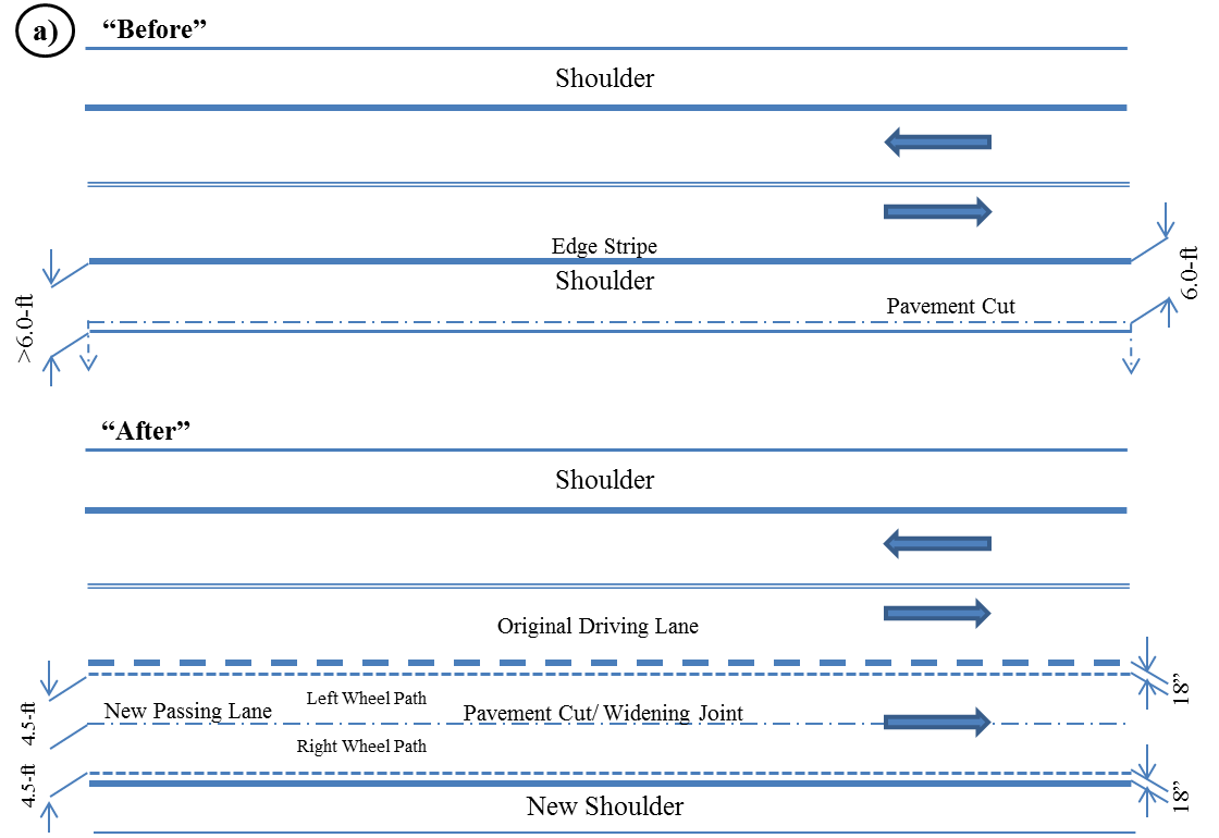
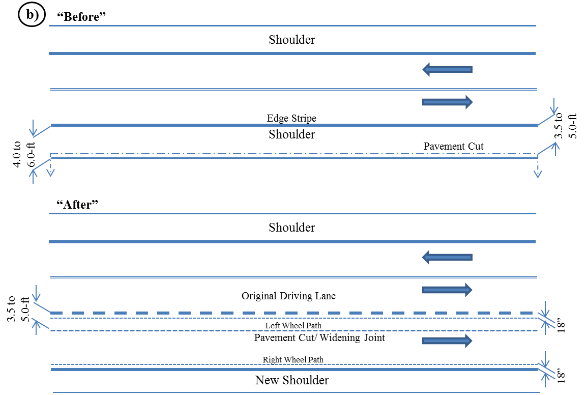
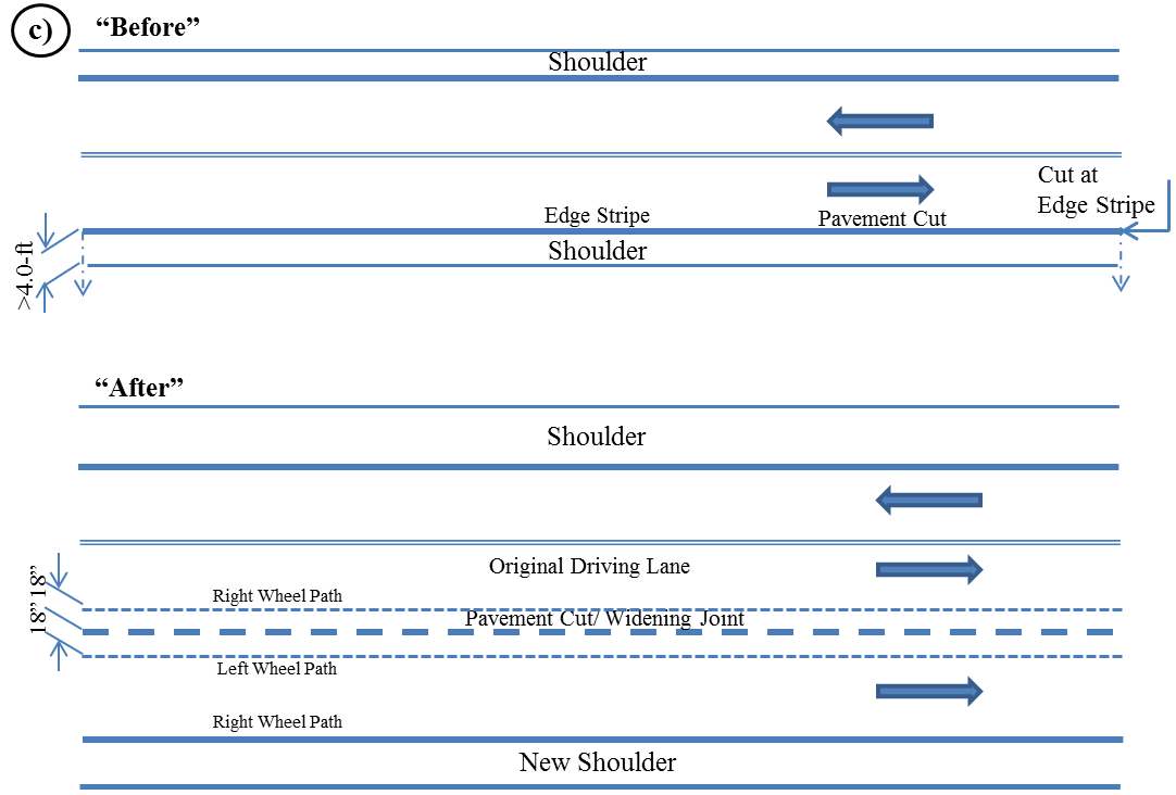
Widening a 2-lane structure for the purpose of developing a Super2 or 4-lane cross section will entail additional considerations for cut locations and shoulder structural analysis when the existing shoulder may form part of a new driving lane. When the shoulder is to form part of a new lane, non-destructive surveys using the falling weight deflectometer (FWD) are essential. In addition, ground penetrating radar (GPR) may prove to be a useful preliminary survey tool to determine whether the shoulder matches the current driving lane in structure. Recommendations for pavement cut locations for Super2 construction are shown in Figure 5-2.
Figure 5-2. Recommended Widening Joint Location: a) 12.0-ft. Lanes, Original Shoulder > 6.0-ft. width, b) 12.0-ft. Lanes, Original Shoulder 4.0- to 6.0-ft. width, and c) 12.0-ft. Lanes, Original Shoulder < 4.0-ft. width.
5.2.1. Recommendations for Similar Cross Section Widening Strategies
The objective will be to match as close as practical the same cross section and materials in the widened section as were used in the original section.
5.2.1.1 Unbound Granular Base Sections
Other considerations are:
- Anchor: #NFEAVNXV
- Treatment of the subgrade under the widened location. This may serve to reduce moisture fluctuations at the new pavement edge which, in turn, should reduce potential for longitudinal edge cracking. An alternative may be to use geogrids at the subgrade/base interface. Treatment should be accomplished below the level of the old flex base. Anchor: #BPBBYYYJ
- When milling any HMA to the outside of the existing lane, also remove an extra 12.0 in. to the inside of the existing lane edge (stripe). The object is to offset the HMA joints above the widening interface. Anchor: #CTIQKMUL
- Selection of the new flexible base material should be based on laboratory evaluation of both new and existing materials to compare the moisture susceptibility of each. Preferably, these should be about the same. A material that is more highly moisture-susceptible may draw moisture from both the original section and from outside the structure. A material that is less moisture-susceptible may send moisture into the original base, particularly during the initial curing process. Anchor: #BUWSPFHT
- Apply level-up to match original HMA surface elevation. Make repairs to original surface as necessary. Apply reflective crack retardant (geotextile, SAMI), if desired. Anchor: #ROGDPCVQ
- Apply overlay across full section. Final longitudinal mat joints should be placed at lane stripes when used. Anchor: #UVJFSTWA
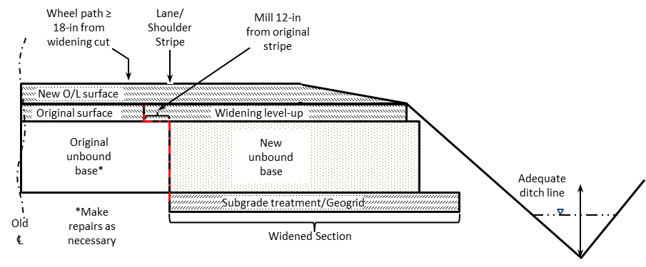
- Ensure ditch lines are sufficient to prevent hydraulic backflow into the pavement structure. Figure 5-3 depicts an example of an unbound base section.
Figure 5-3. Unbound base sections.
5.2.1.2 Bound Base Sections
Other considerations will closely parallel those cited for the unbound base situation. If an original bound base is cement-treated material, there are cases when it may be preferable to use full-depth HMA for the widening to expedite construction. This strategy should not cause subsurface moisture flow problems (“bath tub” effect) when the cement treated base is not itself moisture-susceptible. Laboratory evaluation of core samples will reveal the degree of moisture susceptibility of the existing base.
5.2.2 Recommendations for Dissimilar Cross Section Widening Strategies
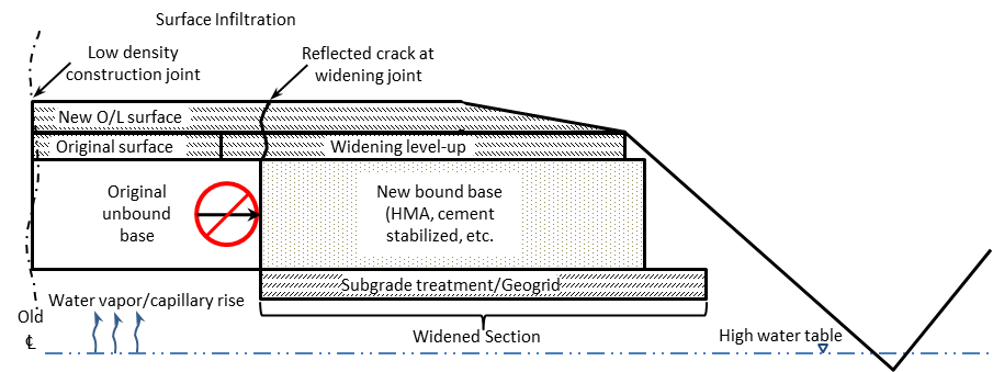
This widening strategy is not encouraged because it often results in lateral subsurface drainage restrictions (see Figure 5-4 “bath tub” effect). If it was possible to guarantee that no moisture would accumulate beneath the surface of the original structure, this type of widening would be easier to endorse.
Areas of the state that experience low rainfall and deep water tables may experience better performance with this type of widening strategy. If this type of widening is considered in wetter areas, consideration should be given to installing subsurface drainage at the widening interface, with laterals to the ditch line (Chapter 2, Section 8). Unfortunately, this remedy is generally counter to expediting construction. Sources of in-pavement moisture accumulation are shown below.
Figure 5-4. In-pavement moisture accumulation, resulting in “bath tub” effect.
