Section 4: Non-Destructive Evaluation of Pavement Structural Properties
Anchor: #i10091394.1 Introduction
Urgency of the design, importance of the highway, value of the project, and availability of non-destructive tools usually influence what testing is performed. However, proper evaluation is essential to ensure performance; there is no substitute for comprehensive planning that includes reserving the equipment when needed.
The most common structural-based non-destructive tools used in TxDOT are discussed in some detail in the Flexible Pavement Rehabilitation Strategies Training Course located in the Maintenance Division website under the Pavement Engineering link. Practical exercises in the use of analyses software for data collected by these systems are also included in this course.
Anchor: #i10046494.2 List of Non-Destructive Tools in Order of Availability
The general order of availability for non-destructive tools is as follows:
- Anchor: #ODWMUETL
- Falling Weight Deflectometer (FWD). These systems are scheduled through the Pavement Evaluation office (Pavement Preservation, MNT) at (512) 832-7210.This device is essential in establishing the in situ stiffness properties of the pavement layers through analysis of the deflection data by backcalculation of layer moduli values using MODULUS. Moduli can then be used as design inputs to FPS 21. Anchor: #YDLGHXJO
- Dynamic Cone Penetrometer (DCP). Many districts have purchased their own (roughly $2500 per unit). Units are also available at MNT – Pavement Asset Management. This portable device is a secondary tool used to verify unbound pavement layer thicknesses, confirm the presence of lime stabilized subgrade, and evaluate the relative stiffness and uniformity of support of unbound layers. It can prove useful in verifying MODULUS layer inputs and moduli outputs. A correlation equation developed by the Army Corps of Engineers is used to convert DCP data to moduli values. The DCP requires the boring of a small pilot hole through bound materials. Anchor: #JXVTXVDA
- Air-coupled Ground Penetrating
Radar (GPR). These systems are scheduled through the
Pavement Evaluation office (Pavement Preservation, MNT) at (512)
832-7210. When department-operated systems are not available on
short notice, the Texas A&M Transportation Institute (TTI) operates
a system that may be available through an interagency contract managed
by MNT – Pavement Asset Management.
This is a van-mounted system that provides a nearly continuous profile of layer thicknesses and dielectric variations to a maximum depth of about 24 in. beneath the pavement surface. Dielectric properties are correlated to material density and moisture content so subsurface problems (stripping, trapped moisture) in the existing HMA and excessive moisture in base layers can be detected.
GPR can also be used to identify segregation and low density in existing HMAs. GPR testing of PCC pavements has not been as successful as testing on HMA and surface treated pavements due to the GPR signal interference by the reinforcing steel and the attenuation of the signal through PCC materials.
- Anchor: #KADKCKTB
- Ground-coupled Penetrating Radar (GPR) testing is available from MNT – Pavement Asset Management and through an interagency contract with TTI that is managed by MNT – Pavement Asset Management. GPR testing involves pushing by buggy or towing one or more GPR antennae along the ground at walking speeds. Some antennae operate at a lower frequency than the air-coupled GPR units and, therefore, penetrate much deeper into the pavement and underlying layers. The trade-off with lower frequency antennae is poorer near-surface resolution. Ground-coupled GPR has been used to locate sink holes, search for buried underground objects, such as abandoned storage tanks, or test for water damage, underground utility problems, or other anomalies that are deeper than an air-coupled GPR unit can sense. These systems can explore anomalies under either flexible or rigid pavements. Anchor: #KXDDWBPX
- Seismic-based tools (Portable
Seismic Pavement Analyzer [PSPA], Dirt SPA [DSPA], V-meter, Free-free
Resonant Column). Contact MNT – Pavement Asset Management
for availability of these devices.
The SPA series of devices are used in the field to measure in situ properties. These devices are used to generate seismic waveforms in the material being tested. The elastic modulus at small strain is proportional to the velocity of the wave propagation.
The V-meter and Resonant Column are laboratory instruments used to measure properties of samples collected in the field or molded in the lab. These devices use a pin or hammer “source” to impact the pavement or sample surface. Wave propagation speed and analysis of the wave dispersion curves can be used to determine layer thickness, stiffness with depth, and presence of discontinuities (cracks, delaminations). Seismically-derived stiffness values are evaluated at very low strain and require adjustments to be used for determining values comparable to ones estimated at higher strains, for example, truck wheel loads.
Anchor: #FJEDTUBA - Total Pavement Acceptance Device (TPAD). The TPAD was developed under a department research project that concluded in August 2012. Further implementation was authorized under a 2-year project through August 2014. The TPAD combines the capabilities of Rolling Dynamic Deflectometer (continuous deflection measurements) and air-coupled GPR surveys. Additionally, high definition video, linear offsets, high-precision differential GPS coordinates, and surface temperature logging of the pavement section are conducted concurrently. Coordinate use of this device through MNT – Pavement Asset Management.
4.3 Falling Weight Deflectometer (FWD)
The falling weight deflectometer (FWD) is a trailer-mounted device that places an 11.8 in. (300 mm) diameter load plate in contact with the highway at each test location. The testing interval is set at 0.1 mi. (maximum) or a minimum of 30 locations per project. A load column above the load plate carries a stack of weights that are dropped to impart a load to the pavement similar to that imparted by a passing dual truck tire set. A series of seven geophones spaced away from the load plate at 12-in. increments measure the surface deflection, generating a “deflection bowl.” Measurements are generally acquired in the right wheel path of the outside lane. The latest upgrade to the FWD includes an 8th geophone mounted 12 in. from the load plate opposite sensor #2. This sensor facilitates evaluating load transfer across joints and cracks on rigid pavement. GPS coordinates are also automatically posted to the deflection file for each tested location.
. (click in image to see full-size image)")
Figure 4-4. Falling Weight Deflectometer (FWD).
")
Figure 4-5. Falling Weight Deflectometer, detail view.
Where a divided roadbed exists, surveys should be taken in both directions if the project will include improvements in both directions. Some care in the placement of the load plate and sensors is required by the survey crew, especially where the highway surface is rutted or cracked. The load plate should lay on a flat surface; the load plate and all geophones should lie on the same side of any visible cracks. A human spotter should be used to ensure placement in these cases.
Temperature data collected at the time of testing is necessary for all flexible pavements since the modulus of bituminous materials is temperature-dependent. The FWD has a built-in thermocouple to measure ambient air temperature and an infrared sensor to measure surface temperature, and records these temperatures at each drop location. In addition, for pavements with bituminous surfaces at least 3.0 in. thick, in-pavement temperature measurements should be made at the beginning and end of each survey, at a minimum. Longer surveys or surveys made on days where rapid temperature changes occur will require temperature checks at additional intermediate locations. A portable drill with masonry bit can be used to accomplish this; holes are drilled to mid-depth or 3.0 in. maximum. Alternatively, surface temperatures measured by infrared devices can be made with correlations available for mid-depth temperature estimation. The Modulus Temperature Correction Program (MTCP) can be used for this purpose. This program is available through the department’s MNT intranet page, under Engineering Applications.
Liberal use of comments placed in the FWD data file at the time of data collection is encouraged. Comments pertaining to offset from reference markers and bridge abutments, or proximity to patches, cracks, etc., are all important documentation for the individual evaluating the data. Interpretation of collected deflection data can be based on simple comparison of the normalized (for load) maximum measured deflections, or can be much more rigorous, for example, by using backcalculation methods or evaluation of deflection time-histories. Detailed discussion on the backcalculation methodology of layer moduli for flexible pavements is found in Chapter 5, Section 4, FPS21 Modulus Inputs and Backcalculation Methodology.
Description of the FWD with conceptual discussion on basic operation is given in the Flexible Pavement Rehabilitation Strategies training course available through the department’s MNT intranet page, under Pavement Engineering.
4.3.1 Evaluating Deflection Data for Load Transfer on Rigid Pavements
Efficient load transfer across joints and cracks on rigid pavements is necessary for good performance. Deterioration of cracks and joints through spalling, widening, ruptured steel, erosion of subbase support, and moisture and incompressible materials intrusion will tend to reduce the load transfer efficiency over time. Evaluating the existing load transfer efficiency is necessary to formulate an appropriate rehabilitation strategy. For example, if the level of efficiency is above 70%, an HMA overlay may be an appropriate rehab strategy. Load transfer in concrete slabs is significantly influenced by ambient temperatures; higher temperatures will cause cracks and joints to close, thereby improving aggregate interlock and load transfer. For comparability and veracity of results, all testing should be accomplished at relatively steady temperatures below 80°F. In a typical load transfer setup with the FWD, the FWD is initially positioned with the load plate edge tangent to the crack or joint to be tested, with the W2 sensor positioned on the opposite side of the joint or crack as shown in Figure 4-6.
")
Figure 4-6. FWD setup to measure joint load transfer.
The AASHTO ’93 Design Guide defines load transfer efficiency as:
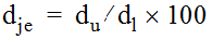
Where dje is the joint efficiency; du is the deflection on the unloaded side; and dl is the deflection on the loaded side. First, the deflection at W2 is du, measuring efficiency from the approach slab perspective. Then, the FWD is pulled forward with the load plate tangent to the joint from the departure slab perspective, and W8 is du. W1 will be the dl in both cases. Whichever measurement indicates the lower efficiency should be used for rehab considerations.
Another methodology for determining load transfer efficiency is to use deflections at the crack or joint compared to that at center slab. First, the FWD is positioned at center slab (away from working joints/cracks) and deflection measurements at the W1 and W2 sensors are noted (W1cs and W2cs, respectively). Then, the FWD is moved forward to the joint to be evaluated and the load plate is positioned tangent to the joint on the same slab, with the W2 on the opposite side of the joint as in the AASHTO procedure. Deflection measurements at the W1 and W2 sensors are noted (W1jt and W2jt, respectively). Load transfer efficiency is determined as:

Similarly, the evaluation can be performed with the load plate tangent to the joint on the adjacent slab, where the W8 sensor will be used in the above formula in place of the W2jt reading.
The customary Dynatest FWD data file (.fwd file extension) used by TxDOT for backcalculation will only report data for the first seven sensors. However, current FWD survey data protocol saves all sensor data in a small MS Access database, from which data may be extracted to conduct load transfer efficiency calculations.
Anchor: #i10048264.4 Dynamic Cone Penetrometer (DCP)
This portable device complies with ASTM D 6951 and consists of a 2-piece rod; the lower rod is about 39 in. long (1 m) and is fitted with a replaceable cone tip at the penetration end and an anvil at the upper end. The anvil houses a threaded or shear pin receptacle for attaching the upper rod. The upper rod carries the 17.6-lb. sliding hammer and has a handle for steadying the device during testing. The hammer free-fall distance on the upper rod is 22.6 in.
. (click in image to see full-size image)")
Figure 4-7. Dynamic Cone Penetrometer (DCP).
4.4.1 DCP Operation Instructions
The operator drives the DCP tip into the soil by lifting the sliding mass (hammer) with one hand to the handle then releasing it. The other hand holds the instrument by the handle to maintain an approximate vertical position. If a bound layer (HMA, PCC, cement-stabilized base) is present above the non-bound layers, a 1.25 in. hole should be first bored through the bound layer(s).
4.4.2 DCP Readings and Data Collection
An initial depth reading is made using a measuring stick/tape between the bottom of the sliding mass and a stationary surface (pavement surface, ground level, etc.). The total penetration for a set of blows is measured and recorded by an assistant. A plot of depth vs. cumulative blows is generated, and a trend line is fitted to the data points for each tested layer. The penetration rate in mm/blow is determined as the slope of the trend line.
A separate trend line should be generated for each layer containing only data points measured in that layer. Dividing the data into discrete segments in this manner ensures that only valid data points can influence the trend line's slope.
The number of blows in a set can vary; for softer soils, 1-3 blows may be a set; whereas, for stiffer soils, 5-10 blows may be a set. Some soils may be so stiff that little to no penetration is recorded in a given set. Results of testing in flexible base materials with larger aggregates can often be invalidated when the cone attempts to drive an aggregate through the base material matrix. Under these circumstances, it is better to halt testing and bore/drill down to a lower level, or restart the test adjacent to the initial location. Any time drilling is done before the start of a DCP test, the first data point should be at the actual start depth and the person processing the data will not include the surface (zero depth) as a data point, since this would invalidate the penetration rate (mm/blow) calculation.
At the conclusion of the test, the instrument is extracted by tapping the mass upward (vertically, avoiding an arc) against the handle or by using a jack attached beneath the anvil. Both methods have some risk of damage to the instrument; in softer soils, when using a disposable cone, tapping the mass against the handle is the most expeditious method.
The Army Corps of Engineers has developed a number of correlations relating rate of penetration to soil stiffness in terms of California Bearing Ratio (CBR). For most applications, the following relationship is adequate for approximating in situ stiffness.
CBR = 292/PR1.12
Where:
- Anchor: #ANNLHSJX
- CBR = California Bearing Ratio, Anchor: #PHRTMENO
- PR = penetration rate, mm/blow.
This relationship has been further correlated to elastic modulus (E) using the relationship:
E = 2550 x CBR0.64
Where:
- Anchor: #KJQUYLTJ
- E = elastic modulus.
Plots can be made to show the relationship of stiffness with depth. This procedure is useful for determining the effective depth of a granular base, the effectiveness of lime stabilized subgrade, or whether there are soft pockets of material with depth. Visual examination of the DCP shaft, once extracted, can also reveal the presence of free moisture. Basic operation and example problems are presented in the Flexible Pavement Rehabilitation Strategies training course.
Anchor: #i10049264.5 Air-coupled Ground Penetrating Radar (GPR)
This van-mounted self-contained system carries a data acquisition boom-mounted antenna off the front of the vehicle, suspended above the roadway. This allows for uninterrupted data collection at near-highway speeds. The system sends pulses of radar energy into the pavement and captures returned reflections from each perceived layer interface within the structure. A survey is generally run in the right wheel path with data summarized at 10-ft. intervals; the effective width of the scanning is about 8.0 in. If data is needed at other transverse locations along the lane, additional parallel passes must be made.
. (click in image to see full-size image)")
Figure 4-8. Air-coupled Ground Penetrating Radar (GPR).
")
Figure 4-9. Detail view during calibration.
The 1-GHz antenna has a maximum penetration depth of about 24 in. The amount of energy returned and the time delay between reflections are used to calculate layer dielectrics and thickness. The dielectric constant of a material is an electrical property that is most influenced by moisture content and density. As the density and moisture content go up, the amount of energy reflected increases (and the penetrating ability decreases). Conversely, if the air voids increase, the amount of energy reflected decreases. Typical dielectric values for various pavement materials are given in Table 4-1 below:
|
Material |
Dielectric |
|
|---|---|---|
|
Typical Range |
Signal Attenuation |
|
|
HMA |
5 - 7 |
Low |
|
HMA - stripped |
< 4 |
Low |
|
HMA w/light weight aggregate |
3 - 4 |
Low |
|
HMA - wet (surface or voids) |
> 8 |
Moderate |
|
Open Graded Friction Course, Plant Mix Seal, Permeable Friction Course |
3.5 - 4.5 |
Low |
|
OGFC w/light weight aggregate |
2 - 4 |
Low |
|
Microsurfacing |
3.5 - 4.5 |
Low |
|
Flex Base - dry |
< 8 |
Low |
|
Flex Base at optimum moisture content (OMC) |
8 - 12 |
Low |
|
Flex Base - saturated |
> 16 |
High |
|
Cement Treated Base |
7 - 9 |
Low |
|
Clay - wet |
> 20 |
High |
|
Concrete - old |
8 |
Moderate |
|
Concrete - new |
10 - 20 |
High |
|
Air |
1 |
Low |
|
Water |
81 |
High |
|
Ice |
3 |
Low |
4.5.1 Analysis of GPR Data
Analysis of raw GPR data is accomplished using the PaveCheck software. This program is available through the department’s MNT intranet page, under Engineering Applications. PaveCheck has the capability of evaluating and presenting both FWD deflection data and GPR data for the same project simultaneously. The PaveCheck user’s manual is available through the same MNT intranet link. Also, basic concepts of GPR and example problems are presented in the Flexible Pavement Rehabilitation Strategies training course. This training aide is somewhat dated in that the older COLORMAP software (not compatible with current computer operating systems) is discussed. Because of the capabilities to compute material dielectric properties and layer thicknesses, GPR has become a valuable tool to the pavement engineer to assist in determining the following:
- Anchor: #DSSFWBJY
- layer thicknesses, section changes, full-depth patches, Anchor: #PRXRFLWV
- location and extent of potential problems, such as elevated moisture levels or stripping in the HMA, and Anchor: #PQPHUAFE
- location/extent of segregation and low joint density.
Verification of suspected problem areas should be made with targeted coring and sampling. These sites should be selected based upon the analysis results from PaveCheck; locating potential coring sites based on radar signature patterns is facilitated by high definition video and GPS coordinates collected in the radar survey. Conclusions drawn from this limited sampling can then be applied with more confidence to the remainder of the survey.
Anchor: #i10049964.6 Ground-coupled Penetrating Radar (GPR)
GPR systems using lower-frequency antennae are able to discern anomalies deeper within the pavement structure. Resolution is improved when the systems are placed in contact with the surface, so the antenna is pushed by buggy or dragged behind a van that houses the data acquisition system. Typical antennae frequencies used by the department range from 200 MHz to 2.5 GHz. Maximum penetration will vary with antenna frequency, soil type, and degree of saturation. Higher antenna frequency will provide lower penetration, but higher near-surface resolution. Under the right conditions, the 200 MHz antenna can penetrate up to 30 ft.; however, with this lower frequency, there is poor near-surface resolution of layers. These systems have been used successfully in locating buried fuel tanks, archeological burial sites, sink holes, rebar during coring, voids under pavement slabs, honeycombing in concrete, pavement thickness above rebar, and aquatic springs within the right-of-way. The systems and the required data analysis remain specialized; services are available through MNT – Pavement Asset Management or through an interagency contract with the Texas A&M Transportation Institute (TTI).
")
Figure 4-10. 200 MHz Ground-coupled Penetrating Radar.
")
Figure 4-11. 400 MHz Ground-coupled Penetrating Radar.
Anchor: #i10050244.7 Seismic Evaluation Tools
Seismic tools can be divided into two groups: those used in the field for evaluation of in situ pavement properties and those used to evaluate samples in the laboratory.
4.7.1 Field Seismic Tools
Portable and Dirt Seismic Pavement Analyzer (PSPA, DSPA). The PSPA has an enhanced capability to measure the seismic modulus, delamination, debonding, and thickness of the upper strata (i.e., HMA lift) of the pavement structure. The DSPA is similar in configuration, but has a broader hammer surface for use on unbound surfaces. The foot that contacts the surface is an inactive anvil that is struck with an internal striker; the contact piece acts as a wave transmitter. Specialized acquisition and analysis software is loaded on a laptop computer to retain system portability.
")
Figure 4-12. Portable Seismic Pavement Analyzer.
4.7.2 Laboratory Seismic Tools
V-meter. The V-meter is an ultrasonic laboratory device that is particularly useful for testing HMA briquettes (lab-compacted specimens or field cores). In this device, a transmitting transducer is securely placed on the bottom face of the specimen. The transducer is connected to the built-in high-voltage electrical pulse generator of the device. The electric pulse is transformed into a mechanical vibration which is applied to the specimen. A receiving transducer is securely placed on the top face of the specimen, opposite the transmitting transducer. The receiving transducer, which senses the propagating waves, is connected to an internal clock of the device. The clock automatically displays the travel time of compression wave. By dividing the height of the specimen by the travel time, the compression wave velocity and, as such, the seismic modulus of the material, is determined.
")
Figure 4-13. V-Meter.
Free-free Resonant Column. The resonant column device uses laboratory-prepared soil specimens that may be prepared using the Proctor (ASTM D-698), modified Proctor (ASTM D-1557), or any other procedure adopted by the agency. Since the test is non-destructive, a membrane can be placed around the specimen so that the specimen can be tested later for strength (static triaxial test) or stiffness (resilient modulus or cyclic triaxial test). An accelerometer is securely placed on one end of the specimen, and the other end is impacted with a hammer instrumented with a load cell. In less than 3 min., a specimen can be tested, and the test result can be obtained. The process has been automated and simplified so that a technician can perform the test, interpret the results, and generate a report almost immediately.
")
Figure 4-14. Resonant Column.
Anchor: #i10050864.8 Total Pavement Acceptance Device (TPAD)
The Total Pavement Acceptance Device (TPAD) is a truck-mounted system consisting of a rolling deflectometer that applies large cyclic loads to the pavement and measures the induced deflections with rolling deflection sensors as it moves along the pavement, while generating a ground penetrating radar survey coincident with the deflection survey. There are numerous advantages built into this version of a rolling sensor deflectometer, including a low-speed cruise control, improved acquisition software, and survey enhancements, including high definition video, linear distance offsets, high-precision differential GPS coordinates, and surface temperature acquisition. Currently, the TPAD is fitted with three rolling sensors mounted on individual carts connected to an isolation positioning/lifting frame; one sensor is mounted between the loading rollers, one in front of the loading rollers, and the third a similar distance behind the loading rollers. Rolling sensors have been improved, but data collection speed is currently limited to 2 mph to maintain a reasonable signal-to-noise ratio. The TPAD must be transported to the project site with a semi tractor-trailer. Preliminary software was developed for data analysis of all data collected (deflections, GPR signature tied to deflection location, video, longitudinal offsets, GPS coordinates, and surface temperatures). Because of the added surveying features on the TPAD, it is now much easier to physically revisit a problematic location to conduct further non-destructive testing or material sampling.

with detail of loading rollers and front geophone cart. (click in image to see full-size image)")
Figure 4-15. Total Pavement Acceptance Device (TPAD) with detail of loading rollers and front geophone cart.