Section 6: Perpetual Pavement Design and Mechanistic Design Guidelines
Anchor: #i10425916.1 General
Structural Design of Pavements is an evolving process. Gradually, we have moved from purely empirical design relationships based largely on the results of observations at the AASHO Road Test to the current mechanistic-empirical process incorporated in FPS 21, where material stiffness is related to performance (loss of smoothness) through use of the surface curvature index (SCI, a deflection parameter).
Ultimately, the goal is to incorporate other intrinsic material characteristics, the environment, and their interaction under traffic loading, to the progression of specific forms of distress by using mathematical transfer functions. As a result, multiple performance relationships for any given structure subjected to a given regional environment and regional or site-specific axle loads are needed.
In 2001, the Flexible Pavement Design Task Force (FPDTF) studied structurally designed deep HMA pavement; a type of pavement typically associated with high assurance of long pavement life.
As a result of the 2001 study, the following guidelines were established:
- Anchor: #LYNITWJN
- department guidelines for materials to be used, Anchor: #WWLPXVJR
- the general (“conceptual”) structural design format, and Anchor: #LNSOOCQR
- the locations where these structures should be considered.
Current guidelines have taken into consideration design and constructability issues experienced in the structures designed under the original guidelines. Recommended structural layer composition for facilities with a projected 20-yr. one direction cumulative loading of at least 30 million ESALs is clarified. When 30 million ESALs are exceeded, premium mixtures, such as Item 346, “Stone Matrix Asphalt (SMA),” and Item 344, “Superpave Mixtures,” should be used in lieu of conventional QC/QA dense-graded specifications (Item 341) to ensure adequate top-down crack resistance in the surface and rut resistance within lower HMA layers. For the fatigue resistance characteristic to be effective, all HMA layers must be fully bonded to allow the system to act as a composite mass. The SMA and Superpave mixes are specifically engineered to offer exceptional performance under heavy traffic loads. Dense-graded mixes under Item 341 may be used as an alternative to the stiff, rut-resistant HMA base layers with prior approval by the director, MNT, or designee.
Along with establishing an engineered foundation, using a dense, low air void HMA bottom layer (Ndes = 35 gyrations or 97.5% lab density) shall be considered when:
- Anchor: #HJATOXOO
- full-depth HMA structures have a composite HMA thickness between 8-12 in., or Anchor: #AUGYBJSD
- there are concerns for bottom-up moisture intrusion into less rich (dryer/higher air void) bottom HMA layer.
6.2 Limiting Strain Criteria
While research continues in this area, there is one “special case” that easily lends itself to mechanistic structural evaluation, albeit without robust regard to reliability. Experts have defined limiting strain criteria with some confidence. If these mechanistic benchmarks are not exceeded, then there is a very high likelihood that the pavement will not suffer traditional bottom-up fatiguing or full-depth (subgrade failure) rutting.
These limiting strain criteria find their full potential in the perpetual pavement design. Thinner structures are generally subjected to similar maximum axle loads, but offer insufficient stiffness or thickness to stay below the limiting criteria. As with other design criteria, these limiting strain criteria presuppose that quality materials are used and that proper construction procedures are followed. The limiting strain criteria reported by experts in the field (such as Nunn and Monismith) are:
- Anchor: #DGXQEBAS
- tensile strain at the bottom of the composite HMA layers: < 70 µ-strain, Anchor: #FCYOJRLL
- compressive strain at the top of the subgrade: < 200 µ-strain.
To develop a design and determine whether these criteria are met is a two-step process:
- Anchor: #VLPJOPPV
- Either the designer must use a program such as FPS 21to roughly estimate an initial thickness design, then use an analysis program that calculates the primary responses to traffic loading for the heaviest anticipated wheel loads for each season of the year at the critical locations, or Anchor: #FUAEHCLC
- the designer speculates at the sufficiency of a desired structure and then evaluates it at the critical locations using a mechanistic analysis program to see what performance life is predicted. Anchor: #HDFMYPHF
- In either case, the design would then be modified to achieve the desired or optimized performance.
6.3 Foundation Design
Special attention is required in designing a durable foundation by investigating the underlying soils to determine the appropriate type, level, and depth of stabilization needed. In lieu of subgrade stabilization, a high quality granular base, cement-treated base, or other engineered foundation can be used. Detailed design and construction considerations are provided in Figure 5-5.
Figure 5-5. Perpetual Pavement Design.
|
Layer |
Layer Composition |
Spec Item |
Preferred Mix Size |
Preferred Lift Thickness |
PG Grade |
Ndes |
|---|---|---|---|---|---|---|
|
A |
Renewable surface
SMA (or SP) or two-layer system PFC on top of SMA (Passing Balance Mix Design criteria) |
Item 342 (PFC
Item 346 (SMA)
Item 344 (SP) |
SMA-D |
1.5 in.
2.0 in.
2.0 in. |
76-XX
76-XX
76-XX |
50
50
50 |
|
B |
Seal Cost |
Item 316 or 318 |
Grade 4 or 4S |
-- |
-- |
-- |
|
C |
Rut-Resistant HMA Base |
Item 344* |
SP-B |
4X nominal maximum aggregate size each lift |
70-22** |
50 |
|
D*** |
Dense Bottom Layer |
Item 341 |
D |
2.0 - 3.0 in. |
64-22 |
35 (SGC); or 97.5% lab density (TGC) |
|
E |
Prepared Pavement Foundation |
1. Item 247
2. Item 275
3. Item 260
4. SS 3003 or SS 3063 |
Grade 1/2
Min 200 psi UCS after conditioning
Passing Tex 121E Part 1
Passing Test methods 122E or 134E |
6 - 12 in.
6 - 12 in.
8.0 in.
6 - 10 in. |
PG 64-22 or CSS 1H |
-- |
|
F |
Natural subgrade |
-- |
-- |
-- |
-- |
-- |
|
* Preference should be given to designing above the reference zone. Substitution of Item 344 mixtures using Item 341 is permitted after consulting with MNT – Pavement Asset Management. ** Use PG 70-22 or higher grade for all HMA mixes that fall within the top 6.0 in. of the finished pavement surface. *** Can be eliminated if total HMA layer greater than 10 inches thick. NOTE: See Construction Considerations in figure above, layer E. Must be designed to pass a strength test - contact MTD for details. |
||||||
Anchor: #i1044590
6.4 Designing a Perpetual Pavement Using FPS21
A summary of the steps to design perpetual pavement using FPS 21 follows.
|
Step |
Action |
|---|---|
| 1 |
Pavement design Type 7 (User Defined) is recommended for this type of structure. |
| 2 |
Select a 30-yr. analysis period. |
| 3 |
Use a confidence level of ‘C’ (95%). |
| 4 |
Use lane distribution reduction factors when three or more lanes are planned in one direction to adjust the 20-yr. cumulative 18-kip ESALs. |
| 5 |
Enter the 20-yr. cumulative ESALs (or adjusted ESALs) in the 18-kip ESAL field. |
| 6 |
Select a “time to first overlay” of 15 yr. |
| 7 |
Follow general guidelines for all other inputs. Note elevated moduli values are permitted for all HMA layers based on total thickness. Select the red arrow button to run the design. |
Steps 1-3: Use pavement design Type 7 for this type of structure since perpetual pavements typically have more than 4 unique layers. Careful attention is emphasized for the selection of structural layers as recommended above under Section 2, Types of Flexible Pavements. Select a 30-yr. analysis period. The analysis period will not be critical, since staying reasonably below the limiting strain criteria specified above is the ultimate goal. However, just meeting the criteria does not ensure adequate reliability (i.e., just meeting the 70 µ-strain criterion could mean a high probability of failure when not accounting for poor design, material variability, or construction practices). Set the FPS confidence level to ‘C’ (95%). This confidence level is not tied to the limiting strain criteria, but is useful in ensuring a reasonable beginning thickness to evaluate further.
Steps 4 and 5: Use lane distribution reduction factors when three or more lanes are planned in one direction. Adjust the 20-yr. cumulative ESALs, if needed, with an appropriate reduction factor; then enter the adjusted 20-yr. ESALs into FPS. The FPS program converts the 20-yr ESALs to 30-yr ESALs for the selected analysis period.
Step 6: Select a minimum “time to first overlay.” Fifteen years is recommended because this time frame will usually allow development of a structure of sufficient depth to meet the limiting strain criteria and still ensure a reasonable reliability. Establishing a “time to first overlay” may not appear to be consistent with “perpetual” design. Actually, the performance module within FPS 21 is inconsistent with perpetual design. The FPS-calculated overlay will not be a structural requirement, but should reasonably mimic an almost certain requirement for “surface renewal” to mitigate the effects of surface wear, oxidation, top-down cracking, etc.
Step 7: Follow general guidelines for all other inputs, with particular attention to serviceability indices and material moduli. Ensure a permanent foundation layer that accounts for environmental variability (including poor soils and moisture fluctuation) is included in the design. Select the red arrow button to run the design.
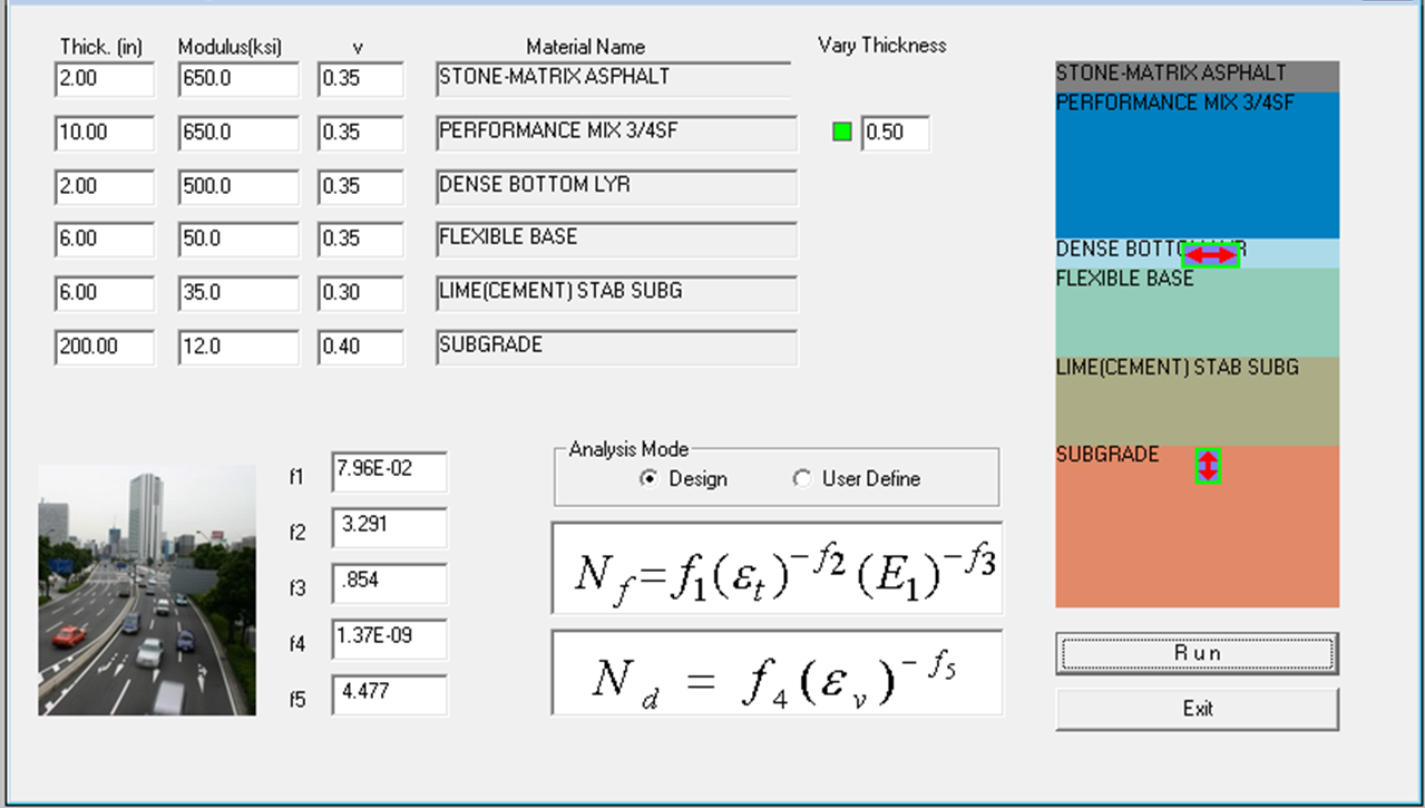
Depending on the thickness ranges selected, the resulting designs may indicate a requirement for an overlay prior to the end of the analysis period. (NOTE: Analysis period is not entirely pertinent to the development of a perpetual design in FPS, but serves as a rough gauge/reminder that one or more surface renewals will be needed over the design life.) Conduct a design check of the limiting strain criteria by activating the FPS 21 mechanistic check. Figure 5-6 shows a typical perpetual pavement setup in the mechanistic check input screen. Ensure that the horizontal red arrow tensile strain indicator symbol is placed at the lowest HMA interface by dragging it into place. The “vary thickness” green sensitivity button shall be dragged adjacent to the layer that the designer would most likely change the thickness of to optimize the design.
Figure 5-6. Mechanistic Check Input Screen.
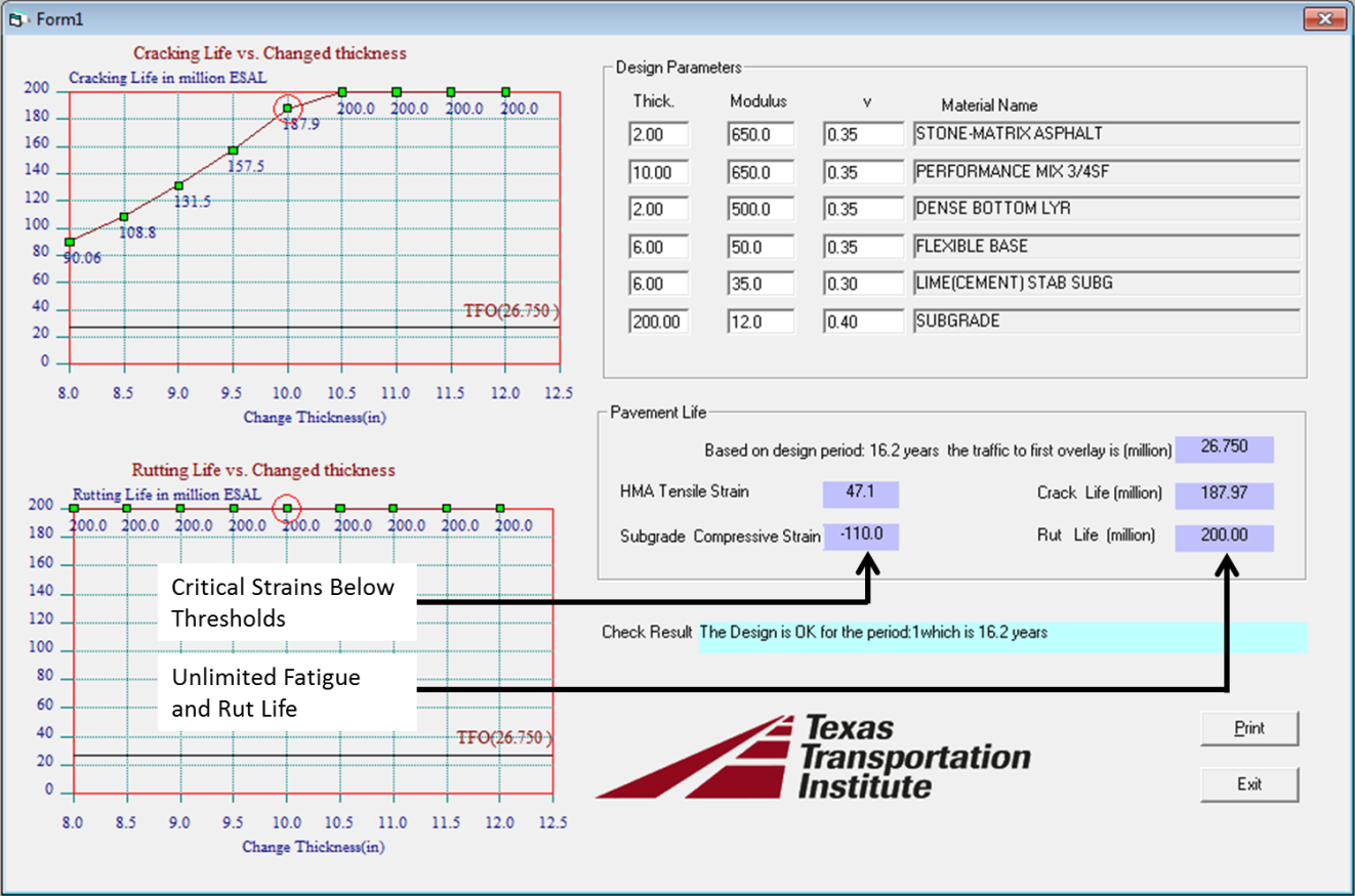
By selecting the run button on the input screen, the mechanistic check output screen must show strain results below the limiting strain thresholds previously cited for bottom-up fatigue cracking and compressive failure of the subgrade (rutting) for the design to be valid. Also, the check will report “unlimited” fatigue and rutting life (> 150 million ESALs), as shown in Figure 5-7 below. For a thorough discussion on the use of the FPS Mechanistic Check feature, refer to the FPS 21 User’s Manual.
Figure 5-7. Mechanistic Checks Output Screen.


