Section 7: Joints
Anchor: #i10200987.1 Introduction
Concrete undergoes volume changes due to temperature and moisture changes. If these volume changes are not controlled properly, excessive stresses will develop, resulting in uncontrolled cracks. These cracks can be sources of distress that could be avoided if properly controlled. Joints can be considered as intentional cracks and are provided where the cracking is most likely. These joints relieve stresses, thus preventing uncontrolled cracks. Provisions are made at the joints to provide wheel load transfer.
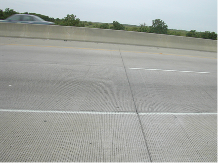
In CRCP, however, the concrete volume changes are controlled by random cracks, which are held tightly closed by longitudinal reinforcing steel. Figure 9-68 shows an example of random cracks in CRCP. These random cracks do not cause distress.
Figure 9-68. Random cracks in CRCP.
There are three types of joints in rigid pavements:
- Anchor: #OKILHNWD
- Contraction joint, Anchor: #LPFHMMPG
- Construction joint, Anchor: #YOYDMLOS
- Expansion joint.
7.2 Contraction Joints
Contraction joints are used to relieve tensile stresses resulting from temperature drops and moisture variations in concrete. The contraction joints can be longitudinal contraction joints or transverse contraction joints.
A longitudinal contraction joint is required when the concrete placement width is more than 15 ft. because the chances of cracking, in the longitudinal direction, increase. In normal concrete pavement construction, the width of the concrete placement varies and can be as wide as 50 ft. The saw-cut depth of a longitudinal contraction joint should be 1/3 of the slab thickness. For CPCD, single piece tie bars are spaced at 24 in. to keep the two adjoining lanes together. For CRCP, in addition to the transverse steel, single piece tie bars are spaced at 48 in. to keep the two adjoining lanes together.
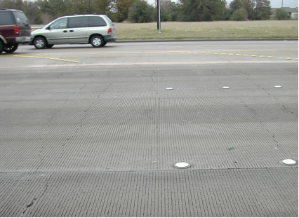
Transverse contraction joints are used only in plain-jointed pavement (CPCD). An example is shown in Figure 9-69. This type of joint is sawn into the green concrete (concrete will not spall or ravel at the cut edges). CPCD standards require transverse contraction joints to be sawed every 15 ft.
Figure 9-69. Transverse contraction joint.
Dowel bars are provided at the transverse contraction joints to provide load transfer, which reduces deflections and stresses due to wheel load applications. To allow the slabs to move freely in the longitudinal direction due to temperature and moisture variations while providing efficient load transfer, dowel bars are lubricated at least one-half of their length.
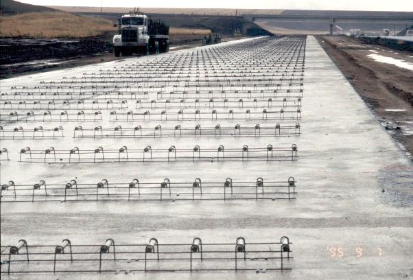
The detailed requirements for dowels, such as dowel bar size, length, and spacing, are shown in the CPCD Standards. Figure 9-70 shows a picture of a dowel bar assembly.
Figure 9-70. Dowel bars.
Dowel bars are typically placed in heavy welded wire baskets that hold the bars in proper spacing, depth, and alignment. Full-lane width baskets are typically used, although baskets that are one-half of the lane width have also been used. These wire baskets are shop fabricated. Typically, one end of the dowel bar is tack-welded to the wire basket. The wire basket is nailed to the base to prevent the basket from being pushed along the base once submerged under concrete and under the paving machine.
Alternatively, dowel bars may be mechanically placed by the paving machine. When this method is used, it is important to ensure that the bars are properly aligned and positioned. When this equipment is first used, a few bars should be carefully exposed using a small trowel to verify alignment and positioning. This is done from a work bridge behind the paving machine. Whether wire baskets or mechanical inserters are used, it is extremely important the dowel bars be parallel for the contraction joint to function properly.
Problems can occur when longitudinal and transverse contraction joints are sawn too late or too shallow. Attempts to saw-cut too early might cause raveling of aggregates, while saw-cutting too late might result in uncontrolled cracking. There are a number of factors that determine the optimum time of saw-cutting. They include, but are not limited to, setting characteristics of concrete, ambient and concrete temperatures, and thermal coefficient of concrete. Even though it is possible to theoretically determine the optimum time for saw-cutting, it is almost impossible to do at the job site due to so many variables involved. The best strategy is to saw-cut as early as possible without causing severe raveling. Item 360 allows some minor raveling due to early saw-cutting.
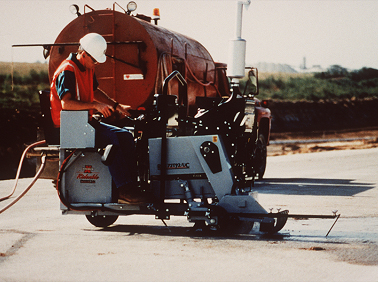
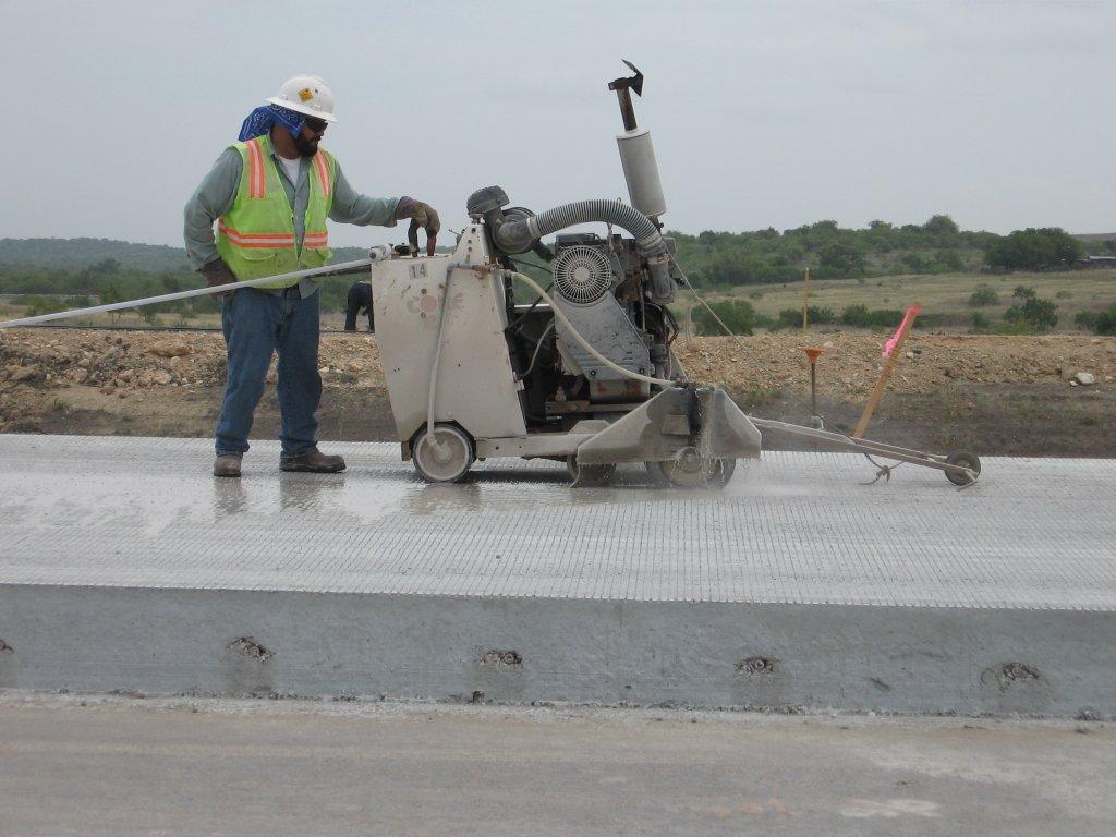
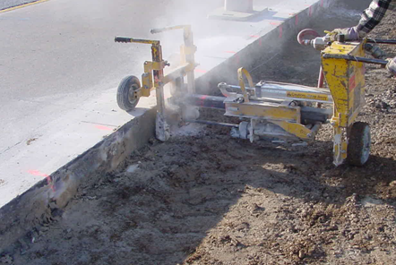
Concrete saws are self-propelled and rotate their blades in a cut-down direction, unlike a handheld circular saw which rotates its blade in a cut-up direction. Most concrete saws use diamond-tipped saw blades which require water to cool and lubricate the blade. Some saws are riding saws, like a riding lawnmower (see Figure 9-71), and others are self-propelled walk-behind saws (see Figure 9-72). Some newer saw models do not require the use of water and can actually saw the concrete earlier than the concrete saws shown here. These saws are typically called “early entry” saws and are specially designed to minimize raveling.
Figure 9-71. Riding saw.
Figure 9-72. Walk-behind saw.
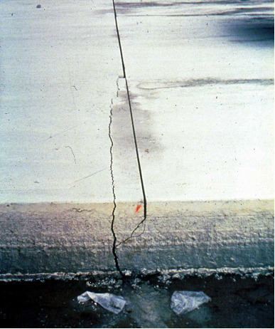
Figure 9-73 shows that the initial saw-cut was being made from the top of the figure to the bottom. For some reason, the initial saw-cutting was delayed. When the saw was halfway across the pavement, the concrete cracked ahead of the saw.
Even if the crack is sealed and allowed to stay in place, the concrete between the crack and the saw-cut will eventually spall out. To prevent uncontrolled cracking, every second or third transverse joint should be sawed first then the intermediate joints. This is called skip-sawing.
Figure 9-73. Uncontrolled crack developed while initial sawing. The left side of the slab needs to be removed and replaced.
Depth of the joints also plays a role in ensuring the proper working of the joints. Shallower cuts than specified will increase the chances of the pavement cracking somewhere else. The saw cut depth must be a minimum of 1/3 of the slab thickness for CPCD pavements and longitudinal contraction joints in single mat CRCP. For longitudinal contraction joints in double mat CRCP, saw cuts are a depth of 4 in. Saw cutting should be accomplished as soon as possible without damaging the pavement, regardless of time of day or weather conditions. Once the saw-cut is completed, it is cleaned and sealant materials are applied. TxDOT’s standard for sealing joints can be found in http://www.dot.state.tx.us/insdtdot/orgchart/cmd/cserve/standard/rdwylse.htm.
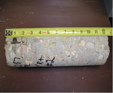
Figure 9-74 shows a 12-in. thick pavement with an actual saw-cut depth of approximately 2.5 in. The required saw-cut depth is 4.0 in. As a result of the shallow saw-cut depth, a crack was not induced at the desired joint.
Figure 9-74. Crack was not induced due to shallower saw-cut depth than required.
Anchor: #i10206937.3 Construction Joints
Construction joints can be longitudinal or transverse. A transverse construction joint is formed when the paving operation is stopped because of the end of the workday or because of a mechanical breakdown. A longitudinal construction joint is formed when two adjoining lanes are placed with separate concrete placements.
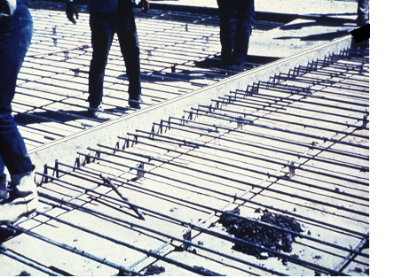
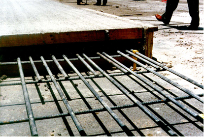
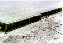
For transverse construction joints, provide a bulkhead (header) that is of sufficient cross sectional area to prevent deflection, accurately notched to receive the load transmission devices, and shaped accurately to the cross section of the pavement (see Figure 9-75).
For CPCD, install a transverse construction joint either at a planned transverse contraction joint location or mid-slab between planned transverse contraction joints. Install tie bars of the size and spacing used in longitudinal joints for mid-slab transverse construction joints. For CRCP, additional longitudinal steel is required (see Figure 9-76). Protect the reinforcing steel immediately beyond the transverse construction joint from damage, vibration, and impact. Splicing of longitudinal steel is not allowed within 10 ft. of a transverse construction joint.
Figure 9-75. Bulkhead (header).
Figure 9-76. Additional steel is required at header.
For longitudinal construction joints, the short pieces of reinforcing steel across the joints are called tie bars. The tie bars keep the two adjoining slabs from pulling away from each other and keep the surface across the joints flat. In Item 360, either single piece tie bars or multiple piece tie bars are allowed at the longitudinal construction joints. The detailed requirements for tie bars, such as length, size, and spacing, are shown in the Standards.
One-piece tie bars may be used when they do not interfere with traffic or construction conditions. The tie bars are inserted manually or mechanically in the concrete that is still confined by the slip-form paver. Larger finishing machines have the capacity to mechanically insert the tie bars evenly with little disturbance to the plastic concrete. When inserting one piece tie bars, caution is needed to avoid hitting the reinforcing mat with the tie bars. It is recommended to insert tie bars a few inches away from the transverse bar locations to avoid displacing the mat. Insertion by hand often causes the edge of the plastic concrete to drop down and requires constant remedial work. Figure 9-77 shows a surface drop down due to hand insertion.
Figure 9-77. Surface drop down due to hand insertion.
Check tie bar insertion depth and locations during paving operations to ensure proper placement. Care must be taken to prevent any movement of the tie bars after placement. Figure 9-78 shows an example of a wood side form at a transverse construction joint. The tie bars at this side form location were not inserted into the plastic concrete. A hole will be drilled and filled with epoxy grout for each tie bar not originally placed.
Figure 9-78. Wood side form at a transverse construction joint.
Multiple piece tie bars are threaded in the middle to allow the two halves of the tie bar to be separated and then reconnected prior to the casting of the adjacent pavement. Finish multiple piece tie bar assemblies from the approved list of DMS – 4515, “Multiple Piece Tie Bars for Concrete Pavements.”
In the past, bent tie bars were commonly used to keep the tie bars from interfering with traffic or construction. After the concrete set, the bent tie bars were straightened to the proper position. This practice is no longer allowed, since there were problems due to the weakening of the tie bar which leads to steel rupture and lane separations.
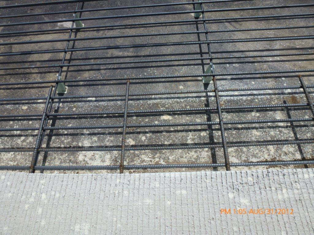
Figure 9-79 shows the spacing of the transverse steel and the spacing of the tie bars in a CRCP section.
Figure 9-79. Tie bars.
Tie bars are also used in plain jointed concrete pavement. When these tie bars are used to connect two lanes, or a lane and shoulder, the tie bar may be mechanically inserted by the paving machine into the fresh concrete ahead of the float, or it may be held in position by support devices. Unlike CRCP, there is not an available mat of steel reinforcement that can be used to position and secure the tie bars. Each tie bar will need to be separately supported and held in position by stakes or pins driven into the base. These supports need to be sturdy enough to hold the tie bar in position when concrete is placed and consolidated over it.
Tie bars are required at longitudinal widening joints for CRCP and CPCD. Provide #6 bars at 24 in. spacing for 8-in. and thicker slabs. Use #5 bars at 24 in. spacing for less than 8-in. thick slabs. Refer to the CRCP standard for the longitudinal widening joint details.
Mark the tie bar locations and drill holes into the existing concrete at least 10 in. deep. Use a drill bit with a diameter that is 1/8-in. greater than that of the tie bars. Figure 9-80 shows the drilling operation being performed at a widening joint. When manufacturer’s instructions are available, precisely follow the requirements for cleaning the holes as outlined. Clean the holes with a wire brush and compressed air to remove all the dust and moisture. Follow the epoxy manufacturer’s instructions to apply the epoxy. Insert the tip of the epoxy cartridge or the tip of the machine applicator to the end of the tie bar hole and inject Type III, Class C, epoxy to fill the entire hole, then insert the tie bars.
Demonstrate, through simulated job conditions, that the bond strength of the epoxy-grouted tie bars meets a pullout strength of at least 3/4 of the yield strength of the tie bar when tested in accordance with ASTM E 488, within the Epoxy manufacturer's recommended curing time. Increase embedment depth and retest when necessary to meet testing requirements. Perform tie bar testing before starting widening work.
Figure 9-80. Marking and drilling holes at widening joint.
Anchor: #i10209557.4 Expansion Joints
Concrete experiences volume changes due to temperature and moisture variations. When the temperature changes, concrete contracts and expands. The resulting expansion of the concrete pavement must be taken into account. Normally, concrete pavement is abutted to bridge structures via approach slabs. If the pavement expansion is not accounted for, the approach slabs will be pushed into the bridge and can cause serious damage to the bridge structures. To prevent this problem, a mitigation system is installed at the bridge and pavement interface to account for the expansion. There were three systems in use by the department:
- Anchor: #MNWLKYMR
- Expansion joint system, Anchor: #VHMLOJLX
- Wide-flange system, Anchor: #GLMNQWTX
- Anchor lug system.
The basic premise of the expansion joint system is that the expansion joint width will be able to absorb any concrete pavement expansion without transmitting the compression forces to the bridge structure.
The wide-flange system is similar to the expansion joint system, except that the expansion joints exist under the wide flange and are not seen from the pavement surface. One advantage is that, since the joint is not exposed to the pavement surface, joint maintenance is minimized.
An anchor lug system tries to restrict the concrete movement at the interface between bridge and pavement by providing several anchor lugs.
TxDOT has investigated the movements of CRCP near bridges and the effectiveness of these three terminal systems in Research project 0-6326, “Rational Use of Terminal Anchorages in Portland Cement Concrete Pavements.”
The research data has shown that the anchor lug system is not effective in the long run. The stresses generated in soil due to slab expansion at lug walls are large enough to result in permanent deformations in soils. The soil does not retract with the lug when the pavement contracts. The permanent deformations result in voids between soil and lug walls.
Field measurements have indicated that the base friction restrains slab movements effectively. Using coarse texture base, such as HMA, might be the most effective tool to control slab movements. Simple expansion joint systems or wide-flange systems are also effective in accommodating slab movements. Expansion joint systems should cost less than wide-flange systems with comparable performance.
The standard for the anchor lug system was deleted and not replaced. The transverse expansion joint details at bridge approaches are shown in sheet 2 of 2 of CRCP and CPCD standards.
Item 368, Concrete Pavement Terminals of 2004 Standard Specification, was removed in the 2014 Standard Specification. Districts may develop a Special Specification for using wide-flange systems.
Anchor: #i10210717.5 Joint Sealing
The purpose of joint sealing concrete is to reduce infiltration of moisture and incompressible materials into joints for improved pavement performance. Infiltration of water through unsealed joints is the main source of surface water into the pavement structure. Moisture in the pavement foundation can allow loss of slab support from base and subgrade erosion and pumping, which causes concrete pavement distress. Sealing also can prevent incompressible materials from entering joints. Incompressible materials lock joints and create excessive stresses that may cause spalling, blowups, or shattering.
There have been considerable national debate and research efforts on the issues and cost-effectiveness of joint sealing and resealing. The department requires all joints to be sealed in concrete pavement per Item 360, “Concrete Pavement,” and the joint sealing standard.
