Section 2: Full-Depth Repair
Anchor: #i10098802.1 Introduction
In this chapter, Portland cement concrete (PCC) pavement distress types that require full-depth repair are discussed, followed by the repair procedures.
Anchor: #i10046912.2 Pavement Distress Types that Require Full-Depth Repair (FDR)
In concrete pavement contraction design (CPCD), the following distresses require FDR:
- Anchor: #FSYDPCCV
- transverse cracks, Anchor: #DYMNWFKC
- shattered slabs and corner breaks.
Transverse cracks that extend through the depth of a slab occur due to temperature/moisture variations and/or wheel load stress and require FDR. Transverse cracks in CPCD that extend through the depth of a slab are caused by design issues, such as inappropriate slab lengths and deficient slab thickness, or construction issues, such as non-uniform or insufficient base support.
Plastic shrinkage cracks occur when the rate of evaporation from the surface exceeds the rate at which the bleed water is available. Shallow plastic shrinkage cracks (approximately 1 to 2 in. from the surface) are not candidates for FDR unless they occur throughout the slab.
Shattered slabs and corner breaks in CPCD result from design issues, such as deficient slab thickness, or construction/design issues, such as non-uniform or insufficient base support.
In continuously reinforced concrete pavement (CRCP), the following distresses require FDR:
- Anchor: #CILMEICW
- punchouts, Anchor: #GLNMGQUC
- deep spalling.
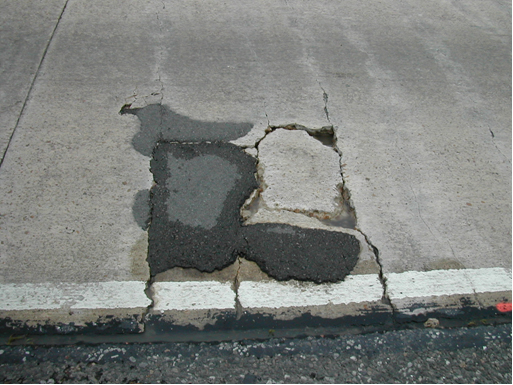
Punchouts in CRCP are caused by design issues, such as deficient slab thickness, or construction/design issues, such as non-uniform or insufficient base support. It is manifested by depressed block(s) of concrete bordered by transverse and longitudinal cracks. Longitudinal steel crossing transverse cracks at the punchouts will eventually rupture, resulting in further deterioration of the punchout. Punchouts are the most serious distress type in CRCP. Improved design and construction practices by the department over the past several decades has significantly reduced the frequency of punchouts. Figure 10-1 shows a typical punchout. Note the asphalt patch was applied to restore the surface elevation, implying that the concrete block was pushed into the base or raveled out.
Figure 10-1. Typical punchout in CRCP.
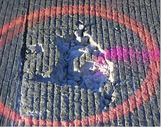
Spalling is another distress type in CRCP. Spalling is the breaking, chipping, or fraying of concrete at the cracks. There are several causes for this type of spalling. In Texas, spalling is more prevalent when coarse aggregates with high coefficient of thermal expansion are used. The depth of spalling varies widely, from less than half an inch to as deep as half the slab thickness. Shallow spalling causes functional rather than structural problems in PCC pavement which can be repaired by half-depth repair (HDR). A series of deep spallings cause substantial structural damage to the pavement and should be repaired by FDR. Based on the severity, durability, and cost, the engineer will determine using FDR or HDR to repair the deep spallings. Figure 10-2 shows deep spalling.
Unlike punchouts, it is not easy to distinguish deep versus shallow spalling. The most efficient way to identify deep spalling is by coring or non-destructive testing, such as ground penetrating radar (GPR), portable seismic pavement analyzer (PSPA), or ultrasonic tomography device (MIRA).
Figure 10-2. Deep spalling.
Anchor: #i10047802.3 Full-Depth Repair (FDR) Procedures
Once it has been identified that FDR is required, the procedures below need to be followed:
- Anchor: #KUVNGQCT
- Identify the repair limits, Anchor: #RNBKFYCI
- Saw-cut the perimeters, Anchor: #OLOHQMJS
- Remove the concrete slab, Anchor: #BCSCTRPY
- If needed, remove damaged base, Anchor: #MJIJNLNY
- Drill holes for longitudinal and transverse tie bars or dowel bars, Anchor: #XSWFOFVN
- Provide longitudinal and transverse steel continuity (CRCP only), Anchor: #LNKXWAXK
- Place and finish concrete, and Anchor: #BJGNXCOM
- Restore existing joints.
Each step is explained in more detail.
1. Identify the repair limits.
Item 361 requires the repair areas to be at least 6 ft. long and at least half a full-lane width, unless otherwise shown on the plans.
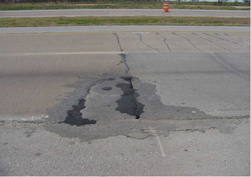
It is important to properly identify the limits of the FDR needed. The repair area needs to include all areas that have developed voids under the concrete pavement. This area typically extends beyond the boundary of the failed areas. It is a normal practice to determine the limits of the repair by evaluating the extent of the distress by visual observations only. Sometimes, this method does not include all the damaged area and results in pavement failures later. Figure 10-3 shows an example of a repair where the limits should have extended farther to the left side.
Figure 10-3. Full depth repair of punchouts in CRCP.
For FDR of extensive transverse cracking and shattered slabs in CPCD, it is a normal practice to remove and replace the whole slab to ease sawing and removal operations. Use good engineering judgment to determine the repair limits for corner breaks.
For punchouts, visual observation of pumping or the use of falling weight deflectometer (FWD) testing can be used to determine the limits of the repair. For deep spalling, coring or non-destructive testing is the most efficient evaluation method. It is recommended that the limits of FDR are extended beyond the limits determined by the evaluations.
2. Saw-cut the perimeters
Once the FDR limits are established, saw-cut the concrete using diamond-blade saws through the full depth of the concrete slab. Saw-cutting with diamond-blade saws will result in a smooth cut surface with little damage to the surrounding concrete. This operation will cut all the existing reinforcing bars along the perimeter. Carbide-tooth wheel saws can cause damage to the surrounding concrete and should not be used for saw-cutting for FDR.
During the summer, saw-cuts should be done in the morning while the concrete temperature is relatively low. When the temperature is high, the concrete is in compression and the diamond-blade saw may bind.
Even though Item 361 allows up to seven days between saw-cutting and concrete placement, the saw-cut concrete blocks should be removed and subsequent repair operations should follow as quickly as possible. When this is not feasible, adjust saw-cut operations so that the subsequent repair operations can immediately follow. Since there is no load transfer in CRCP between saw-cut concrete blocks and the surrounding CRCP, any wheel loading applications will result in higher deflections in both saw-cut boundaries and the concrete block. These large deflections could cause damage not only in the base but also in the concrete, which might increase the repair area needed.
3. Remove the concrete slab
Once the repair limits are saw-cut, the concrete is removed in one of two ways. One method is to lift out large pieces of the slab, and the other method is to break up the slab. Item 361 requires the lift-out method to be used for slab removal. The breakup method is not allowed because it could cause damage to the surrounding concrete.
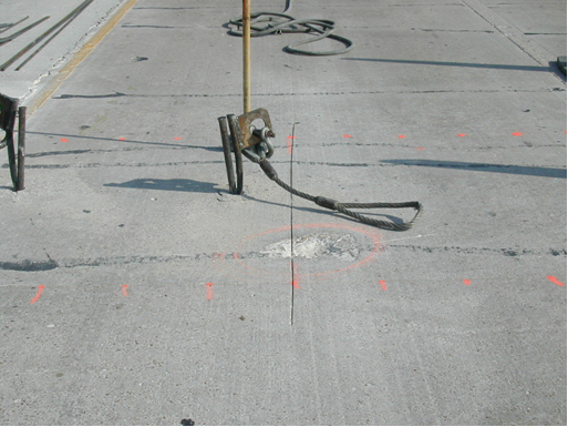
To lift the slab, it is necessary to drill holes and insert pins as shown in Figure 10-4.
Figure 10-4. Slab ready for lifting.
Once the lift pin arrangements are complete, cranes or front-end loaders lift the slab vertically. The lifting should be done as vertically as possible with minimum sway, since any deviation from this can damage the surrounding concrete.
4. If needed, Remove Damaged Base
After the slab removal, remove loose or damaged base material completely, leaving no loose base material. Recompact base materials to the satisfaction of the engineer. When shown on the plans, level the base layer with cold-mix asphalt to the original bottom line and grade of the concrete slab before repair concrete is placed. Place concrete directly onto the compacted base layer unless otherwise directed. Also, if the distress in the base extends beyond the perimeter of the FDR, a decision must be made whether further saw-cutting and additional concrete removal is needed. If the distressed base beyond the perimeter of the FDR is not repaired, the same type of pavement distress will take place.
5. Drill holes for longitudinal and transverse tie bars or dowel bars
If tie bars installed at the repair perimeters are not performing well, the potential problem of lane separation at the longitudinal joint or distresses at the transverse joints will increase.
To achieve the optimum bond between concrete and tie bars inside drilled holes, the holes must be of adequate length, and all dust and moisture inside the holes should be completely removed. The most commonly used method to clean the holes is to use a wire brush and apply compressed air. During this operation, it is important that the air is not contaminated with grease or oil, which will weaken the bond between the concrete and the epoxy. To check whether there is oil vapor, shoot compressed air into white paper for a few seconds and check the paper for oily residue.
Once the drilled holes are cleaned, completely fill with epoxy. The epoxy used in this operation has a low viscosity, and it is difficult to fill the holes completely.
In CPCD, dowels need to be provided at all transverse joints when removing whole slabs. A minimum of four dowels are recommended for each wheel path. Dowel bars can be provided by either drilling and epoxying or by performing a dowel bar retro-fit procedure.
When removing two adjacent half slabs, tie bars must be provided at the transverse construction joint by drilling and epoxying. Provide dowel bars at the new transverse contraction joint and saw-cut and seal the new joint.
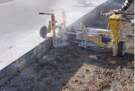
Regardless of which repair type described above is used, provide tie bars at the longitudinal construction joint by drilling and epoxying. In CRCP, provide continuity of the reinforcing steel at the transverse construction joints by drilling and epoxying tie bars. Provide tie bars at the longitudinal joint by drilling and epoxying. The spacing and depth of the holes are specified in the concrete pavement repair standard. Figure 10-5 shows the drilling operation using a single drill. Sometimes, a multiple drill system, called a gang drill, is used for higher efficiency.
Figure 10-5. Drilling holes at longitudinal joint.
The department requires a minimum length of the drilled hole of 10 in. and requires the contractor to demonstrate that the installation process meets the specified pull-out strength. If the specified pull-out strength is not met, increase the embedment depth and retest. Other variables can be modified to increase the pull-out strength such as epoxy application and hole cleanout. Failure of drilled and epoxied bars to achieve proper pull-out strength is generally related to inadequate filling of drilled holes with epoxy rather than the length of embedment.
6. Provide longitudinal and transverse steel continuity (CRCP only)
For FDR of CRCP, this step of providing longitudinal continuity of tie bars is of utmost importance.
The concrete repair standard requires a minimum lap length of 25 in. for #6 bars. To prevent pull-out failure, the steel embedment length should be a minimum of 33 times the diameter of the reinforcing steel. This will work as long as there are no cracks near the transverse perimeter of the repair area. If cracks develop near the transverse perimeter, this requirement will not be met, and the lap length will need to be increased.
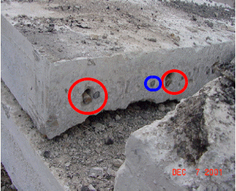
Figure 10-6 shows a full-depth repaired slab that was removed to repair additional distresses that occurred in the adjacent slab. The additional distress occurred because the continuity of the longitudinal steel was not provided in the original repair. The bars in the red circle show tie bars inserted into the drilled holes during the previous repair. The bar in the blue circle is the existing longitudinal steel. It is noted that the tie bars are not fully bonded to the concrete and the holes are not filled completely with epoxy. If pull-out testing had been performed, it would have indicated a possible failure. The inability of the tie bars to provide continuity of the longitudinal steel caused a wide transverse joint, which resulted in additional distress.
Figure 10-6. Previously repaired slab.
7. Place and finish concrete
Once the steel placement is complete, concrete is poured and finished. Since the concrete placing is done manually in FDR, the consolidation of concrete is achieved by hand vibration. In order to provide a good bond between the steel and concrete, a high quality consolidation operation is required. Surface texturing comparable to the surrounding concrete should be provided.
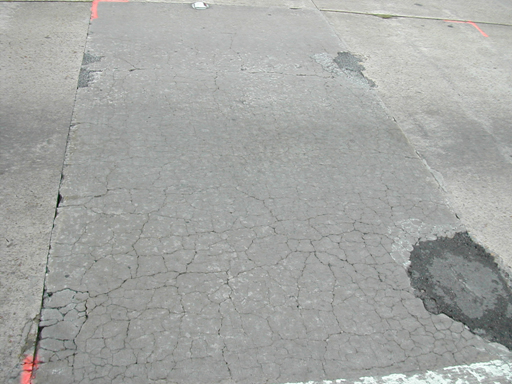
Normally, the full-depth repaired pavement is required to be opened as soon as possible. Item 361 requires the use of class HES concrete if the pavement has to be opened within 72 hr. after concrete placement. Since high early strength is required for early opening to traffic, it is normal practice to use a high cement content as well as Type III cement. This practice could be beneficial if the repairs are done in winter when the ambient temperature is not conducive to achieving high early strength. However, if the repairs are done in the summer when the ambient temperature is high, the practice could result in high heat of hydration and premature pavement distress due to thermal cracking problems. This practice could also result in larger drying shrinkage of the concrete, especially near the surface. As concrete temperature increases, the evaporation of water from the surface also increases. Proper curing is essential to minimize map cracking caused by large temperature gradients and high evaporation. Figure 10-7 shows map cracking caused by improper curing.
Figure 10-7. Map cracking in FDR slab.
If class HES concrete cannot achieve strength within the required time frame, the use of materials meeting the requirements of DMS-4655 is allowed.
For FDR projects, the use of maturity in accordance with Tex-426-A, “Estimating Concrete Strength by the Maturity Method,” rather than conventional strength testing, is strongly encouraged. The accurate estimate of the in situ strength can be best achieved by the maturity method. To use the maturity method, contact the Rigid Pavements and Concrete Materials Branch of the Construction Division.
8. Restore existing joints
Restore all the existing joints within repair area in accordance with the relevant standard joint details and Item 360, “Concrete Pavement.” Especially, perform a timely saw-cut over the dowel bars and restore the transverse contraction joints for CPCD.
