Section 6: Paving Operations
Anchor: #i10158176.1 Introduction
Two types of paving operations are used for the construction of rigid pavement. One is fixed-form paving, and the other is slip-form paving. Both methods have some common operations as further delineated here. First, both methods require accurate survey controls that are used to establish the proper alignment and grade of the concrete pavement. Second, both methods require proper curing of the concrete in order to facilitate producing a durable long-lasting pavement. Third, any required joint sawing must be accomplished in a timely manner to prevent random cracking of the pavement.
Anchor: #i10076006.2 Fixed-form Paving
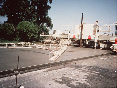
Although not used very often in Texas, paving machines that ride on forms are still in use. Paving machines that use steel wheels to ride on paving forms are very heavy machines, almost comparable to a slip-form paving machine without the drive tracks. To prevent sagging under the weight of this machine, the forms need to be uniformly supported on a very firm base.
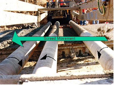
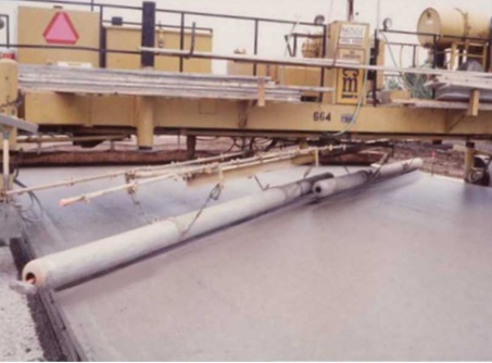
Smaller paving machines, such as the Clary, have three long steel roller tubes that extend across forms in both directions. The rollers propel and screed the concrete to the level of the forms. This type of paving machine is still seen on small and irregular placements, such as ramps and turnarounds. It is limited to smaller productivity and narrower placements.
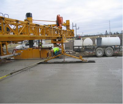
Another type of paving machine that has actually been used in recent years on main lane urban freeways is the Bidwell, a machine that is more commonly seen on bridge deck construction. This machine rides on forms or steel pipes. It is characterized by a truss extending across the forms with a suspended longitudinal screed roller that moves transversely across the pavement. An auger mounted on the front end of the roller screed spreads the concrete, and the roller screed smooths the surface.
Neither the multiple roller-type paver or the bridge-type machine enjoy a reputation for producing a very smooth riding surface and are unlikely to be seen on a pavement surface where a ride specification with bonus/penalty is in effect. Productivity is also relatively low for both types of machines.
Fixed-form paving is a form of concrete pavement construction where fixed forms are used to hold the concrete in place at the proper grade and alignment during construction. This type of paving is different from slip-form paving, which utilizes the forms of the slip-form paving machine to form or mold the concrete in place at the proper grade and alignment, in lieu of fixed forms, during paving. In general, fixed-form paving is not as productive as slip-form paving because of the difference in the efficiency of the placing, spreading, and finishing operations with form riding equipment. In addition, it takes time and effort to set and remove forms before and after paving. However, fixed-form paving is more applicable than slip-form paving in certain situations, such as ramps, blockouts, small paving areas, or where slip-form paving is not feasible or economical. Most of the main lane concrete paving in TxDOT projects is done by slip-form paving. Usually, only minor portions of the concrete paving are done by fixed-form paving.
To facilitate the placing, spreading, consolidation, and finishing operations, concrete used for fixed-form paving usually has more workability or higher slump than the concrete used with slip-form paving.
6.2.1 Forms
A key element in fixed-form paving for constructing a smooth concrete surface is the form. Typical forms have the following characteristics:
- Anchor: #FANTHRQK
- Most of the forms are made of metal with a minimum thickness of at least 0.2 in. and are 10 ft. long. Anchor: #WKYVAQEV
- The height of the forms determines the slab thickness. Anchor: #UXKEIVPF
- The bases of the forms are wide and flat. These wide and flat bases provide stability of the forms while in place. Anchor: #PNOJTSPR
- Flange braces extend outward from the base not less than 2/3 the depth of the form.
The final grade and smoothness of the concrete surface is determined, to a large extent, by how secure and how close the forms are set to the final grade and alignment lines. One of the most important requirements of the forms is to provide stability while concrete is being placed. Unstable forms will cause irregularities in the finished concrete pavement. The top and the face of the forms should be as flat as possible. A straightedge or stringline can be used to check for variance. Forms must be free from detrimental kinks, bends, or warps that could affect ride quality or alignment. The forms should allow for tightly locking the ends of adjacent form sections. The ends of the forms should be flush when they are in position. All forms must be cleaned and oiled before use.
6.2.2 Setting Forms
A survey line is established to facilitate setting forms at proper grade and alignment. Form setting is a critical construction operation since the final grade and smoothness of the pavement surface depends, to a large extent, on how accurately the forms are set to line and grade and how well and uniformly the forms are supported by a firm foundation.
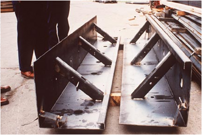
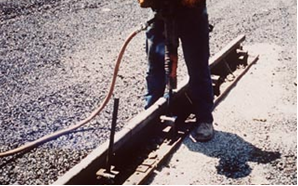
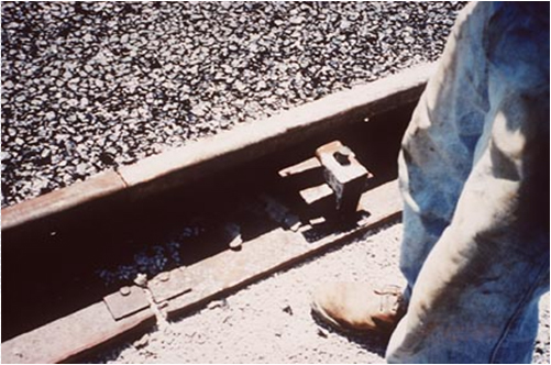
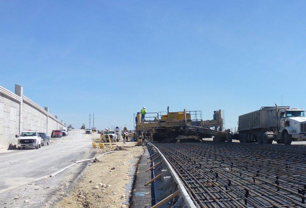
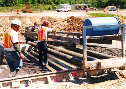
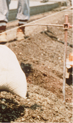
The finished smoothness of the pavement depends on the care with which the forms are set and maintained because the finishing equipment rides on the forms. Proper alignment and elevation of the forms will contribute to a smooth pavement. It is important to provide a firm and level foundation under all forms. Figure 9-21, Figure 9-22, Figure 9-23, and Figure 9-24 illustrate the process of form setting.
Once the forms have been set, they are checked for overall alignment and tolerance before any paving takes place. If any form section is out of line, it needs to be corrected immediately. Joints between forms must be tight and smooth. Specification Item 360 requires that the contractor provide metal side forms of sufficient cross-section, strength, and rigidity to support the paving equipment and resist the impact and vibration of the operation without visible springing or settlement.
Figure 9-21. Forms ready for setting.
Figure 9-22. Using jackhammer to set staking pin.
Figure 9-23. Staking pin.
Figure 9-24. Side forms used for paving.
The preferred depth of the form shall be equal to the required edge thickness of the pavement. Forms with depth greater or less than the required edge thickness of the pavement can be used if the difference between the form depth and the design pavement depth is not greater than 2 in., and:
- Anchor: #ITBJSSHK
- forms of a depth greater than the pavement edge thickness may be used if the supporting material is planed to construct a form trench; Anchor: #MSYNJVLS
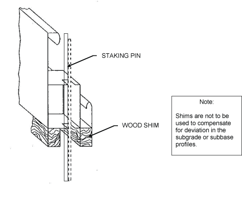
- forms of a depth less than the pavement edge thickness shall be brought to the required edge thickness by securely attaching metal strips or wood shims of approved section to the full width and length of the base of the form, as shown in Figure 9-25. Use grout to fill the gap with wood shims to establish grade.
Figure 9-25. Side form.
6.2.3 Checking Forms
Unlike a slip-form paving operation, where the thickness of concrete pavement can be adjusted for “knots” or rises in the base to maintain proper thickness, the thickness of concrete pavement is established by the height of the side forms. That is, side forms that are 8 in. tall will produce a concrete pavement that is at least 8 in. tall only if the base between the two forms does not have an area that is above the level of the bottom of the forms. To check that there are no bumps in the base, a “scratch” template may be used.
The scratch template is typically a lightweight truss that is supported on the side forms by wheels and has long metal tines spaced about a foot apart that extend down from the truss for the thickness of the concrete pavement. The scratch template is moved along the side forms. If the tines on the scratch template come in contact with the base and “scratch” the surface, that would indicate an area with a rise in the base and where the concrete pavement would have insufficient thickness. If there is a high spot in the base, then that area needs to be milled down, or more commonly, the side forms need to be shimmed up to achieve proper concrete pavement thickness. Base planers were used in the past with side form paving to excavate excess base material. These planers were suitable for use on non-stabilized base materials. Any milling of stabilized base should be approved by the engineer to ensure that no damage to the base or deficient base thickness result.
6.2.4 Paving Operations
As with any paving method, it is important that the concrete be discharged, consolidated, and finished to provide optimum ride quality and long-term performance. Equipment used for placing and finishing concrete in fixed form paving varies substantially from project to project, and detailed descriptions of the placing and finishing operations are not provided in this document.
One of the key elements in fixed-form paving is to maintain a consistent and uniform head of concrete in front of the strike-off screed. The strike-off screed used in fixed-form paving is lighter than the one used in slip-form paving, and too much variation in the head of concrete will result in reduced smoothness of the concrete surface. A head of concrete that does not run over forms or the screed works best. Also, steady machine progress improves pavement smoothness, and concrete should be delivered to ensure steady machine progress.
Finishing operations such as floating, burlap/carpet drag, tining, and curing operations are similar to those in slip-form paving, and they are described under “Slip-form Paving.”
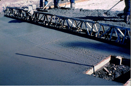
Figure 9-26, Figure 9-27, and Figure 9-28 show how a vibrating screed is pulled forward with a winch at each end of the screed connected to a cable hooked ahead of the screed. A manually operated finishing screed shall be a strike template and a tamping template or a vibratory screed with adequate length to cover the width of the slab.
Figure 9-26. Vibrating screed.
Figure 9-27. A Clary or roller screed.
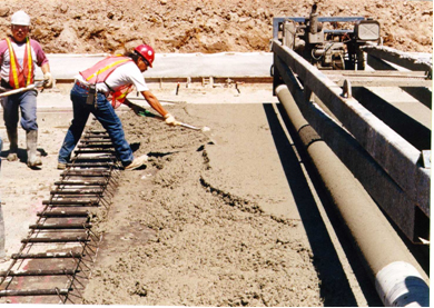
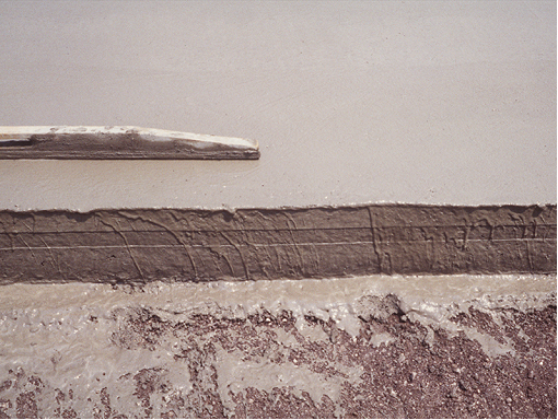
Figure 9-28. Knock down the ridge of mortar formed by the Clary screed.
When the concrete is setting up on the screed and the screed needs to be cleaned, have the contractor move the screed ahead of the concrete so that cleaning water does not fall on the plastic concrete. Figure 9-29 shows the cleaning of the screed between haul trucks.
Figure 9-29. Cleaning screed between haul trucks.
For finishing, texturing, and curing operations, please refer to “Slip-form Paving” below.
6.2.5 Removing Forms
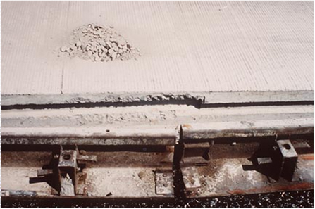
Forms can be removed as early as practical without damaging the concrete. In most instances, forms can be removed within 6 to 8 hr. after concrete placement. The forms shall be carefully removed in such a manner that minimal or no damage will be done to the edge of the pavement. All damage resulting from this operation and any honeycombed areas shall be repaired with a mortar mix within 24 hr. after form removal. Immediately after removing the side forms from the concrete pavement, apply membrane cure to all concrete surfaces not previously treated. Forms should be cleaned right after removal. If not, they become difficult to clean. Figure 9-30 shows removed side forms.
Figure 9-30. Removed side forms.
Anchor: #i10078556.3 Slip-form Paving
Slip-form paving is the most widely used paving method in modern concrete paving construction. The slip-form paver consolidates, screeds, and initially finishes the concrete in one continuous operation without the need of forms. Modern slip-form paving equipment is of the extrusion-type process. The extrusion process can be simply defined as forcing, pressing, or pushing a material through a die or mold to create the desired shape. Slip-form paving is very efficient and can provide smooth concrete pavement. Because there are no forms, the plastic concrete must be able to hold the pavement edge. When slip-forming, the desired slump of the concrete is 1-1/2 in.
6.3.1 Alignment and Grade
The “stringline” is actually a slender wire rope. It is usually tensioned fairly high to reduce sags in the wire between the supports. A sensor on the paving machine will follow the stringline and any sags will show up in the final ride surface as waves that can produce an unpleasant ride quality.
A stringline is established to control the slip-form paving equipment at the proper grade and alignment. A surveying crew establishes a stake line every 25 or 50 ft. along, but offset from the edge of the pavement to be placed. Wood stakes used for this line are about 1-1/2 to 2 in. square, commonly called hubs, and are driven into the ground. The alignment is then established with a tack in the top of each stake. Grade is also established by elevation grading of each stake. For hard, dense subgrade such as an asphalt bond breaker, nails driven into the subgrade are used instead of wooden stakes with tacks. Using the line and grade from this survey line, a stringline is established for the slip-form paving machine to follow utilizing the machine’s electronic grade and alignment controls. Usually, another graded stake line is established along, but offset from, the other edge of the pavement to control the grade of that side of the paving machine; however, alignment is only controlled from one stringline.
6.3.2 Overview of Slip-form Paver
Slip-form paving is accomplished by the use of several self-propelled machines in a line which is commonly known as a paving train.
The first machine in line is a concrete placing machine and, depending on the manufacturer, this machine is sometimes referred to as a placer/spreader. This machine receives the mixed concrete from the delivery vehicles and places and spreads the concrete in front of the second machine, which is the slip-form paver. Sometimes this first machine is eliminated if the concrete can be deposited directly in front of the slip-form paver from the concrete delivery units or if a concrete placing attachment is installed in the front of the slip-form paver.
The slip-form paver spreads the concrete uniformly across the paving area with an auger, consolidates the concrete with spud vibrators, and strikes off the top of the concrete to a suitable elevation to feed into the mold that shapes the pavement into the proper geometric configuration. Depending on the manufacturer, some slip-form pavers also utilize what is known as a tamping bar. The tamping bar slightly tamps large aggregates into the top of the concrete slab to prevent the paver's mold from snagging the aggregate and causing a tear in the top of the slab.
The third machine in the train is a tube float. This machine smooths and seals the top of the pavement by dragging diagonally mounted aluminum tubes forward and back along the top of the pavement. This machine is sometimes eliminated by attaching what is known as an auto float to the back of the slip-form paver. The auto float automatically travels across the top of the pavement while simultaneously oscillating in a forward and back motion to smooth and seal the top of the pavement.
The last machine in the train is a combination tine/cure machine. This machine installs the tining in the pavement top with a metal comb that is automatically dragged across the top of the pavement. This machine is then used to spray the curing compound on the pavement. Sometimes a second curing machine is required if the tine/curing machine can’t perform the curing operation in a timely manner. Either the tube float or the tine/cure machine is also used to install any required texture, such as a burlap or carpet drag texture, after all finishing is completed and prior to any tining texture required.
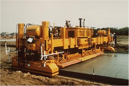
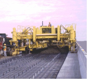
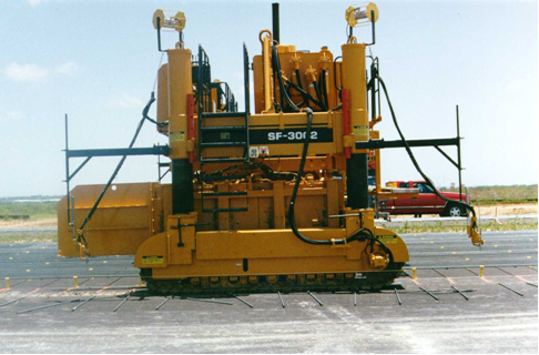
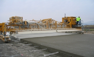
Slip-form pavers contain various combinations of all or some of the following components: auger spreader, spud vibrators, oscillating screeds, clary screed, tamping bars, and pan floats. A slip-form paver is shown in Figure 9-31.
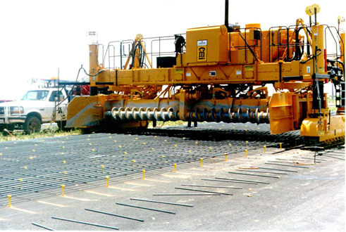
Slip-form pavers are equipped to spread the concrete uniformly and strike off the concrete to the required section, using a power driven device, either a reciprocating blade, a screw conveyor (auger), or a belt conveyor, without loss of traction. A slip-form paver with two augers is shown in Figure 9-32.
Figure 9-31. Slip-form paver.
Figure 9-32. Slip-form paver with two augers (idle).
A machine with two tracks is steered by varying the speed of the tracks from one side to the other side. The bigger machines with four tracks, two tracks on each side, are stirred by pivoting each track, much like the front wheels on a car. The tracks can either ride on the base or on a previously placed pavement. Figure 9-33 shows a paver machine on tracks.
Figure 9-33. Paver machine on tracks.
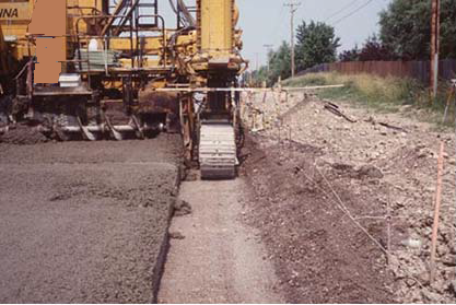
The base should extend out, past the paver’s tracks, to give adequate support for the machine. This is illustrated in Figure 9-34. The track path should be level and clean to allow for a smooth concrete surface. Do not force the grade control sensor to make up for trash, such as spilled concrete or tie bars, in the track path.
Figure 9-34. Track path.
6.3.3 Vertical Alignment Control
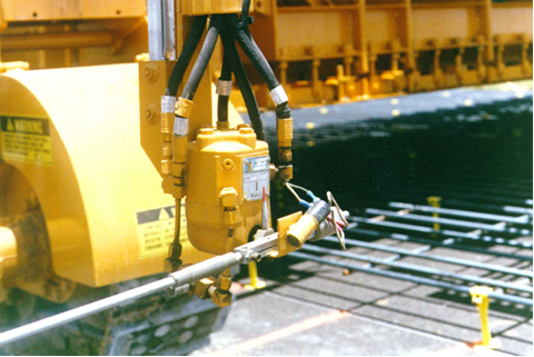
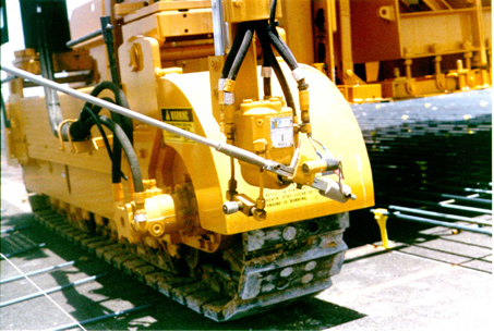
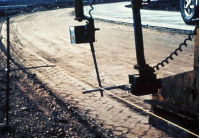
Usually, slip-form pavers have an electronic sensor system or equivalent to provide grade control. Figure 9-35 and Figure 9-36 show examples of such sensors. Sensors come in both electronic and hydraulic models. The electronic sensors work better.
Figure 9-35. Electronic sensor.
Figure 9-36. Electronic sensor.
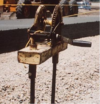
The grade control sensors, one on each side of the paver, have wands that ride on the bottom of a guide wire that adjusts the height of the entire machine by raising or lowering the vertical hydraulic cylinders on each side of the machine. Figure 9-37 shows vertical and horizontal sensors. The guide wire is supported and tensioned to prevent any measurable sag. Figure 9-38 shows the side view of an idle paver. Notice the two hydraulic cylinders on the side of the paver (right side of Figure 9-38). Figures 9-39 and 9-40 show the guide wire controls.
Figure 9-37. Horizontal and vertical sensors.
Figure 9-38. Side view of an idle paver.
Figure 9-39. Guide wire controls.
Figure 9-40. Another view of guide wire controls.
6.3.4 Horizontal Alignment
The alignment or steering of the paver can be either sensor-controlled or operator-steered.
6.3.5 String-less Concrete Paving
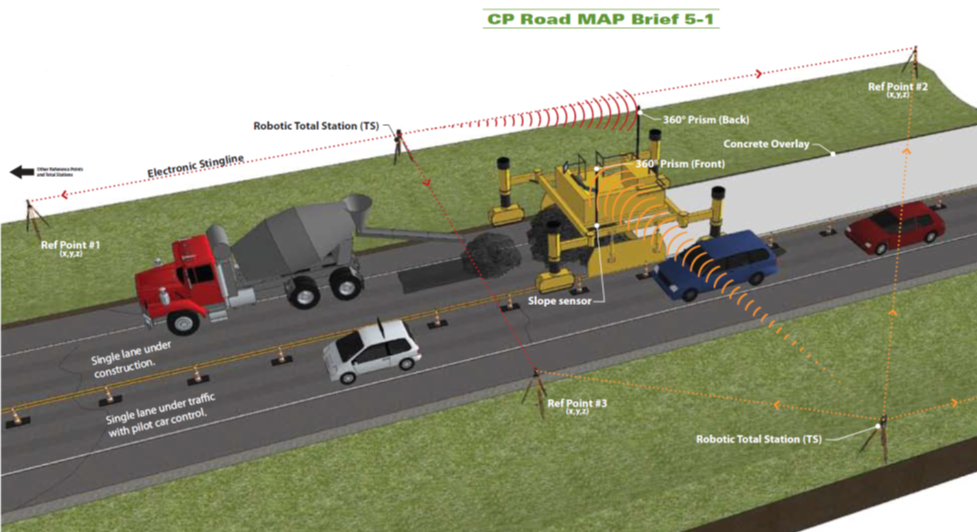
The following information is taken from the FHWA Concrete Pavement Road MAP. Conventional concrete paving with a slip-form paver requires the installation of a stringline and support posts adjacent to the roadway to establish the correct pavement alignment and profile. The stringline adds several additional feet (+/- 6 ft.) of required clearance to the paving envelope, which is already wider than the pavement due to the tracks of the slip-form paver. In addition, the stringline becomes an obstacle for equipment, concrete delivery trucks, and finishing crews. If equipment access across the stringline is required, the stringline must be lowered and reset, resulting in delays and introducing the potential for errors.
String-less paving is a technology that eliminates the installation and maintenance of stringlines and has the potential to decrease the need for surveying and increase the smoothness of the pavement profile. The benefits that can result from string-less paving include increased production, decreased construction time, and reduced potential for errors.
Several companies have developed string-less equipment control and guidance systems using technologies such as global positioning systems (GPS), robotic total stations, and laser positioning. String-less technology replaces the traditional stringlines with an electronic tracking process that controls the horizontal and vertical operation of the slip-form paver. The construction industry has been using string-less technology for elevation and steering control of equipment for a number of years. To date, the extensive use of this technology has been applied to grading operations. However, string-less paving is an emerging technology for concrete paving because it has the potential to allow contractors and owner/agencies to receive production benefits (e.g., reduced survey costs, fewer construction hours) while still meeting smoothness requirements. Figure 9-41 shows the string-less paving machine.
Figure 9-41. String-less paving equipment.
Contractors using string-less paving equipment are still required to establish control points at maximum intervals of 500 ft. and use the control points as reference.
6.3.6 Paver’s Forward Speed
The speed the paver moves forward is controlled by the operator. The speed should be as uniform as possible, but should vary with the rate of concrete delivery so that complete stops are held to a minimum. The paver speed is up to 20 ft. per minute.
If the paver stops moving forward, the vibrators must be turned off within 5 seconds. Continued running of the vibrators will result in segregation of the concrete, forcing water and fines to the surface.
6.3.7 Augers
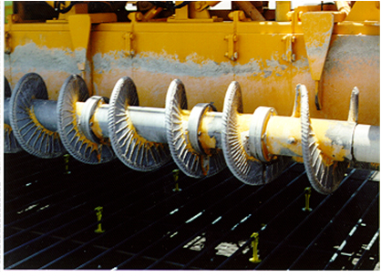
Rotating the augers moves the concrete sideways across the entire lane being paved. The augers are controlled by the operator and can be turned either clockwise or counterclockwise as needed. Figure 9-42 shows a close-up of an auger.
The augers on the spreader of a paving machine help distribute the concrete over the width of the pavement placement ensuring that a uniform head of concrete is maintained across the pavement width and extending well above the vibrators. This overburden over the vibrators helps direct the energy from the vibrators downward into the concrete pavement and helps ensure proper consolidation of the concrete. Figure 9-43 shows the spreading of the concrete.
Figure 9-42. Close-up of an auger.
Figure 9-43. Auger and strike-off spreading the concrete.
6.3.8 Vibrators
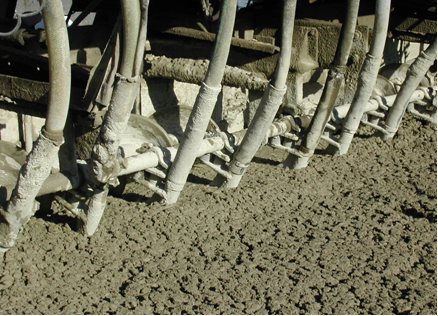
The frequency in air of the immersion vibrator units shall not be less than 8,000 cycles per minute. Figure 9-44 shows immersion of vibrators. Handheld vibrators are driven by an electric motor.
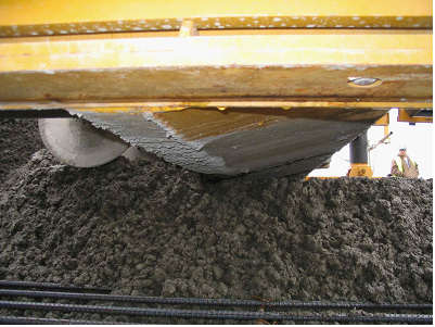
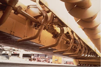
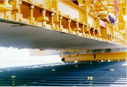
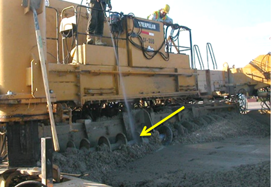
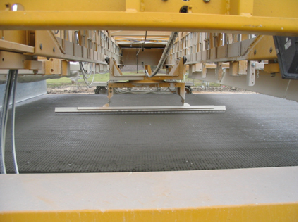
Vibrators on a slip-form paver are hydraulically driven. Figure 9-45 shows the underside of a slip-form. Going from right to left, observe the:
- Anchor: #HFCGGLBN
- augers, Anchor: #ERCAVAVO
- strike-off screed, Anchor: #BRYPIXHR
- vibrators, Anchor: #OWPRSPOU
- finishing screed, and Anchor: #LAAYSLWQ
- pan float.
Vibrators need to be mounted high enough that they will not snag any of the reinforcing steel. An isolated streak in the concrete pavement behind the paving machine may indicate that there is a non-working vibrator.
Figure 9-44. Immersion vibrators.
Figure 9-45. Underside of slip-form paver.
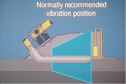
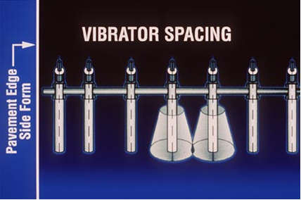
Figure 9-46 shows the normally recommended vibration position. The paver is moving to the left. A concrete head or surcharge should be maintained over the vibrators during placing operations. The vibrators must be turned off whenever the forward motion of the paver is stopped. Figure 9-47 shows the vibrated zones.
Figure 9-46. Normally recommended vibration position.
Figure 9-47. Drawing showing the vibrated zone.
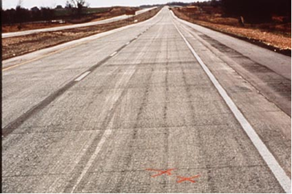
No vibrator streaks or trails should be apparent behind the paver. Figure 9-48 shows unacceptable vibrator streaks. Here, the vibrators are not vibrating enough. Because of this, the vibrators are plowing a trail instead of vibrating the concrete.
Figure 9-48. Unacceptable – vibrator streaks.
6.3.9 Pan Float
After screeding, the concrete surface is finished with a pan float that further smooths and consolidates the concrete. Pan floats are solid plates anywhere from 18 to 60 in. wide and slightly narrower than the pavement width. Figure 9-49 shows pan floats on an idle paver.
Figure 9-49. Looking up at a pan float on an idle paver.
Anchor: #i10186846.4 Placing Concrete
As mentioned above, concrete can be placed in front of the paving operations using a number of methods. Regardless of which method is used, concrete should be placed as near as possible to the final location. Concrete should never be moved using rakes or vibrators, as these methods cause segregation. Concrete should only be moved by the use of shovels or the augers mounted on the spreader and paver.
In order to promote proper hydration, concrete placed should have a temperature between 40°F and 95°F. It is allowed to use the loads that are already in transit when the temperature was found to exceed the allowable limits. Immediate action must be taken or paving operations ceased until the concrete temperature is corrected.
When the ambient temperature in the shade is 40°F and falling, concrete should not be placed. Typical concrete paving mix designs have relatively low cement contents and usually contain fly ash. This combination of materials tends to make the concrete susceptible to prolonged set times and slow strength gains in cold weather conditions, which can lead to plastic shrinkage cracking. If the ambient temperature is expected to drop below freezing, precautions must be taken to ensure the freshly placed concrete is protected against freezing.
Placing concrete during hot weather can also lead to plastic shrinkage cracking if proper curing is not performed as soon as possible after texturing operations. If there is a delay in application of the curing method, measures should be taken to ensure that the unprotected pavement surface is kept from drying. The use of fog sprays, wind screens, or evaporation retardants are acceptable methods to prevent the surface from drying.
Anchor: #i10082486.5 Finishing Operations
6.5.1 Sealing the Surface of the Concrete
To close all surface openings and produce a uniformly smooth and flat surface, the plastic concrete behind the screed is either floated or straightedged, or both.
6.5.2 Floats
A float may be used only when using a finishing machine. Figure 9-50 shows an example of tube floats. Tube floats are pulled back and forth in the longitudinal direction. Notice that each tube float is suspended and pulled by chains. The tube floats are set at 60 degree angles to the pavement’s centerline. The leading end of the tube float may be on either the inside or outside of the pavement. The tube floats must extend across the entire width of the pavement being placed. For wide concrete placements, more than one tube is used.
Figure 9-50. Tube floats.
Tube float machines must have spray nozzles to provide a fine, light fog mist to the concrete surface just ahead of the tubes.
A longitudinal float, also called auto float, slides back and forth in the transverse direction. An example of a longitudinal float is shown in Figure 9-51. Notice the surface marks left by the float.
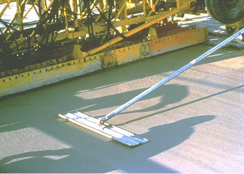
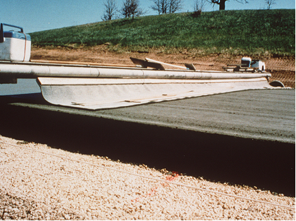
Another type of float is the drag float, an example of which is shown in Figure 9-52. Because a drag float is heavier than a tube float or a longitudinal float, the drag float applies greater surface pressure, making it more effective at smoothing out a knot or bump in the plastic concrete. A drag float needs to be more effective because it only makes a single pass across the plastic concrete.
Figure 9-51. Longitudinal float.
Figure 9-52. "V" shaped drag float pulled by paver.
When using a drag float, be careful that the float does not slowly slide to the downhill side when paving a crowned or superelevated section.
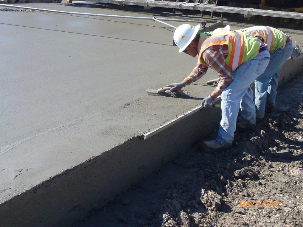
When the float cannot reach to the edges, the edges are floated with hand trowels. Such a process is shown in Figure 9-53.
Figure 9-53. Hand trowel.
Care must be exercised while floating to avoid distorting the surface. A bull float (Figure 9-54) can produce a depression if excessively used in one spot. Longer bull floats will produce better results. Bull floating should be limited to small areas and should not be used to float the entire surface. Avoid using a bull float, if possible.
Figure 9-54. Bull float.
6.5.3 Straightedge
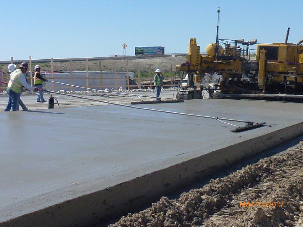
A straightedge is a 10-ft. or 15-ft. long, steel or magnesium, square tube, which contacts the concrete surface. An illustration of straightedge finishing is shown in Figure 9-55 and Figure 9-56. A straightedge flattens the concrete surface and in the case where floats were not previously used, can close surface tears produced by a screed. A straightedge is better at flattening surface bumps and seams than a float, but using a straightedge takes longer than floating because it cannot be mechanized. The straightedges should be parallel to the centerline of the pavement.
Figure 9-55. Straightedge finishing.
Figure 9-56. Straightedge finishing behind a longitudinal float.
Notice in Figure 9-56 that the surface no longer shows the irregularities left by the longitudinal float.
6.5.4 Bleed Water and Free Surface Water
Finishing should be held to a minimum during the period of greatest bleeding since working the surface in the presence of excess water leaches out a portion of the cement and produces low-strength surface mortar. The use of supplementary cementitious materials, such as fly ash and slag cement, reduces bleeding water.
Under calm wind and high relative humidity conditions, the concrete pavement should provide enough bleed water that little or no water needs to be added to float and finish the concrete surface. Under very dry conditions or when there is a strong breeze, the bleed water may evaporate rapidly before floating can be performed. A fine mist of water may be used to reduce the loss from evaporation, but never to form slurry. The fine mist should come from a misting nozzle mounted on a pipe frame that is not pointed directly at the pavement surface.
Water is not allowed to be applied from a nozzle or thumb over a garden-type hose as shown in Figure 9-57. Adding water to the surface makes the finishing easy to perform. However, this practice dilutes and washes away the surface mortar, resulting in poor performance of concrete pavement in terms of skid resistance, scaling, and durability.
If excessive mortar slurry is present during finishing operations (see Figure 9-58) without the addition of water, this generally indicates an issue with the concrete mix. Batch plant operations should be reviewed to correct this situation.
Finishing operations should not be conducted when free water is on the surface of the concrete. Finishing with water on the surface will cause the cement at the surface of the concrete to become diluted or even washed away as shown here. Wait until the water evaporates before continuing with the finishing.
Figure 9-57. Unacceptable - Water being added.
Figure 9-58. Finishing with excessive mortar slurry.
6.5.6 Evaporation Retardants
Once the finishing operation is completed, measures should be taken to keep the surface from drying before the curing compound is applied. It may take a while for the concrete to set up sufficiently after finishing before the texturing can be performed. This delay may increase if the concrete temperature is cool or a high dosage of a set-retarding admixture is used in the concrete mix.
One method of keeping the surface from drying is the use of an evaporation retardant. The evaporation retardant is applied in a fine mist to uniformly cover the pavement surface. An important property, in addition to reducing evaporation, is that it is specifically formulated to not harm the concrete when final texturing of the surface occurs.
The evaporation retardant (see "DMS-4650, Hydraulic Cement Concrete Curing and Evaporation Retardants") should be applied according to the manufacturer’s recommendation when finishing operations cease and maintained until the final texturing occurs. This may be before or after the carpet drag is performed.
Historically, TxDOT has required the contractor to have a small quantity of evaporation retardant (typically in a small garden-type sprayer) on the project to be used if there was a temporary breakdown of the paving machine or a brief disruption in the delivery of concrete. In these circumstances, the contractor would apply the evaporation retardant to the mass of concrete in front of the paving machine to reduce evaporation and keep a crust from forming on the concrete until paving could resume.
Anchor: #i10189656.6 Texturing Operations
Surface texture is required to provide skid resistance and to prevent hydroplaning. Skid resistance is achieved from a combination of the fine aggregate and carpet drag. Hydroplaning is minimized by tining. A carpet drag texture and a metal-tine texture finish are required for all areas with a posted speed limit in excess of 45 mph. When shown on the plans, a carpet drag texture can be the only surface texture required for areas with a posted speed limit less than 45 mph.
When carpet drag is the only surface texture required by the plans, ensure that adequate and consistent coarse texture is achieved by applying sufficient weight to the carpet and keeping the carpet from getting plugged with grout. The target carpet drag texture is 0.04 in., as measured by Tex 436-A. Any location with a texture less than 0.03 in. must be corrected by diamond grinding or shot blasting. The engineer will determine the test locations at points located transversely to the direction of traffic in the outside wheel path.
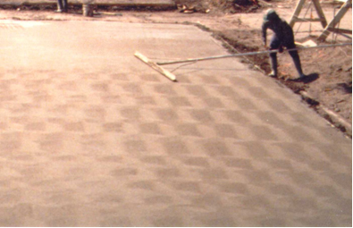
Figure 9-59 shows an upside-down artificial carpet pulled longitudinally on the plastic concrete. This gives the concrete surface a rough texture similar to a broom finish.
Figure 9-59. Artificial carpet drag.
The carpet shall be a single piece long enough to reach across the width of the plastic concrete and having enough longitudinal length in contact with the concrete to produce the desired texture. The engineer may allow changes in the length and width of the carpet to accommodate specific applications.
To keep the mortar from hardening on the carpet, the carpet should first be wetted before using and it should be cleaned with water often enough to produce a uniform finish on the concrete. Streaking of the surface behind the carpet is caused by hardened grout on the carpet. The contractor should stop the drag as soon as the streaking is observed and remove any dried grout from the carpet.
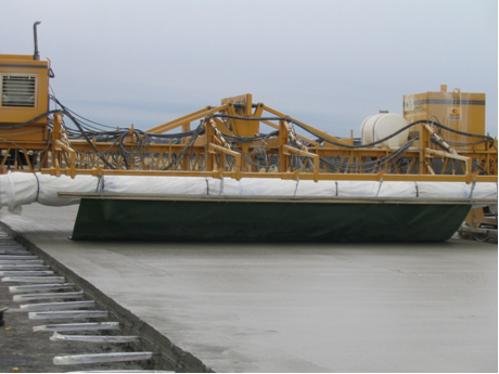
Figure 9-60 shows the mounting of a carpet. The carpet shall be mounted on a movable support system capable of varying the area of carpet in contact with the pavement and can be pulled either mechanically or manually.
To keep the carpet in contact with the concrete, the trailing end of the carpet may be weighted down with something that will provide enough weight to produce the desired texture.
Figure 9-60. Mounting of artificial carpet.
Keep an eye on the drag ‑ it can indicate some things about the concrete. If it starts to catch and pull aggregates to the surface instead of leaving a uniform texture, there are two things that could be wrong:
- Anchor: #HIUFBUWE
- The concrete might not be properly vibrated. Check the vibrators to ensure that all concrete is being vibrated. Anchor: #KCNQOBAA
- There may not be enough sand in the mix to allow grout to be worked to the surface.
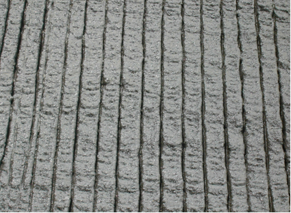
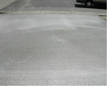
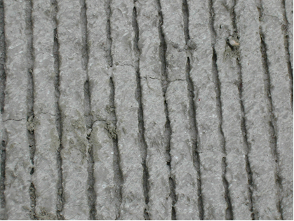
After the carpet drag operation is completed and the concrete surface has set enough, tining operations can begin. The default tining is transverse (see Figure 9-61); however, longitudinal tining is acceptable when shown on the plans. The metal tines should make grooves in the plastic concrete which are 3/16 in. deep and 1/12 in. wide. The minimum groove depth is 1/8 in. The grooves shall be spaced approximately1 in., center-to-center, for transverse tining, or 3/4 in., center-to-center, for longitudinal tining. If noise is a concern, longitudinal tining has been shown to be quieter than transverse tining.
Figure 9-61. Transverse tined Surface.
To ensure that the grooves are straight, the tines should be pulled by a mechanized device. The mechanical device is designed to tine up to a 24-ft. wide concrete pour. Figure 9-62 shows a mechanical tining device.
Figure 9-62. Mechanical tining device.
Anchor: #i10192756.7 Curing the Concrete Pavement
Curing is the process by which hydraulic cement concrete matures and develops hardened properties over time as a result of the continued hydration of the cement in the presence of sufficient water and heat. In concrete pavement, the surface area is relatively large compared with the volume. Moisture can be evaporated from this large surface area unless measures are taken to keep the moisture in the concrete. With loss of moisture, the surface concrete will not develop enough strength and could result in scaling, spalling, and other distresses. It is important that proper curing is provided. The most widely used curing method is the use of curing compound.
6.7.1 Curing Compound
Curing compound should meet the requirements of Type 2 membrane curing compound in "DMS-4650, Hydraulic Cement Concrete Curing and Evaporation Retardants." Curing compound is similar to paint and must be thoroughly agitated just before using. The curing compound should not be thinned or diluted. The curing compound should be re-agitated during its use if it becomes non-uniform.
Two separate coats of curing compound are to be applied to all exposed concrete surfaces. Applying the membrane cure in two coats has several advantages over a single coat:
- Anchor: #FBCELJGD
- it results in a thicker film that better resists evaporation, Anchor: #QGUULJGH
- it reduces rundown of the curing compound into the tine grooves that might occur in a single heavy coat, and Anchor: #RMUBYOLV
- it helps ensure a more even coating of the concrete surface if one or more of the spray nozzles were partially obstructed.
The first and second coats should be applied within 10 min. and 30 min. after completing texturing operations, respectively. The individual application rate should be not more than 180 ft.2/gal.
Where the coatings show discontinuities, pinholes, or other defects, or if rain damages the newly applied curing compound, an additional coat of the compound shall be applied.
Once dried, the curing compound will bead water. If the water does not bead but instead wets the surface of the concrete as determined by darkening the concrete, or by visibly soaking into the surface, an additional coat or coats of the curing compound should be applied immediately.
Should the membrane be damaged from any cause before the expiration of 72 hr., the damaged portions should be repaired immediately with additional compound.
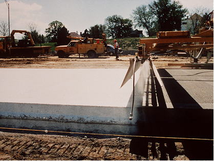
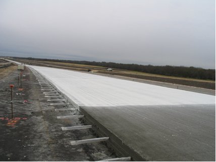
A mechanized spraying unit (see Figure 9-63) is essential when more than one lane of pavement is placed. Note that the machine is applying curing compound to the vertical edge of the concrete as well.
Figure 9-63. Mechanized spraying unit.
Figure 9-64 shows another mechanized unit for spraying curing compound. Note the uniform and complete coverage of the curing compound, even on the side of the concrete.
Figure 9-64. Mechanized spraying unit.
Figure 9-65 illustrates unacceptable application of curing compounds. In this figure, some areas are whiter than others, indicating that curing compound has not been applied uniformly.
Figure 9-65. Unacceptable – non-uniform application of curing compounds.
Plastic shrinkage cracks occurred in the pavement section shown in Figure 9-66 within 5 hr. of concrete placement due to poor curing compound application. This will cause durability problems.
Figure 9-66. Plastic shrinkage cracks.
Figure 9-67 shows that the tie bars have been covered with a plastic sleeve to prevent curing compound from dropping on the tie bars. Any curing compound that ends up on the tie bars or on the “U’s” for the curbs will need to be removed with a steel brush or by sand blasting to ensure proper bonding of the steel to the yet-to-be-placed concrete.
Figure 9-67. Preventing curing compounds from dropping on tie bars.
