Section 5: Reinforcing Steel Placement
Anchor: #i10154355.1 Introduction
In this section, only the placement of longitudinal and transverse rebar is described. The placement of other rebar, such as tie bars and dowel bars, is described in Section 7, “Joints.”
Anchor: #i10074335.2 Reinforcing Steel
The longitudinal steel keeps the naturally occurring transverse cracks in continuously reinforced concrete pavement (CRCP) tight, thereby providing a high level of load transfer across cracks. When transverse cracks are kept tight, aggregate interlock also transmits the shear forces across the crack, resulting in reduced wheel load stress and fatigue damage in concrete.
Transverse steel is used to provide support for longitudinal steel. It also keeps longitudinal cracks tight if they occur.
ASTM A966 Type R bars may only be used as straight bars and only in concrete pavements. This type of bar is permitted to encourage the use of recycled steel in TxDOT concrete paving projects. It may not meet the “pin” test requirements of ASTM and may not have sufficient strength if bent. If this type of reinforcing steel is used in concrete pavement, care must be taken that these bars are not diverted to other uses on the project.
Grade 60 or above deformed steel bars that meet the requirements of Item 440 are used. Grade 70/75 steel bars have been used in some TxDOT projects, and no pavement performance improvements have been noted. On the other hand, when a reduced amount of longitudinal steel was used with Grade 70/75 steel, transverse cracks were wider than those in sections with Grade 60 steel. Cracks with larger widths reduce load transfer across cracks, resulting in larger wheel load stress and poor long-term CRCP performance.
The reinforcing steel should be placed at the locations shown on the plans. As the pavement thickness increases, the amount of steel is increased. For pavements 13 in. or less, all the steel is placed into one mat or layer at the mid-depth of the pavement.
For 14- and 15-in. thick concrete pavements, two layers of longitudinal steel are necessary. Enough room must be provided between adjacent bars to allow the plastic concrete that is placed on top of the steel mat to pass completely through the steel mat to the lower portion of the concrete placement.
5.2.1 Storing Reinforcing Steel
The steel must be stored above the surface of the ground upon platforms, skids, or other supports and shall be protected from damage and deterioration. This prevents excessive rusting that would occur if sitting directly on the ground. It also prevents mud and dirt from collecting on the steel.
When placed, reinforcing steel shall be free from dirt, paint, grease, oil, or other foreign materials. Reinforcing steel shall be free from defects, such as cracks and laminations.
5.2.2 Splicing Longitudinal Steel
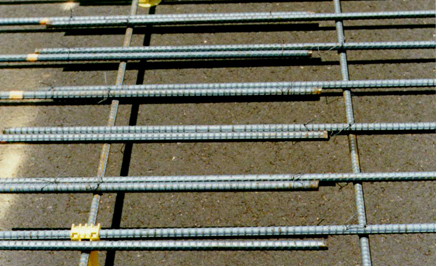
In CRCP, maintaining steel continuity in the longitudinal direction is important in ensuring good performance of the pavement. The length of the longitudinal steel bars is 60 ft. The continuity of the longitudinal steel is achieved by overlapping individual steel bars. Extensive testing shows that as long as the overlapping is more than 33 times bar diameter, stresses in one steel bar is effectively transferred to the next steel bar via surrounding concrete. For example, No. 6 bars would need a 25-in. splice for effective stress transfer. Figure 9-14 shows an example of spliced or lapped reinforcing steel.
Figure 9-14. Spliced or lapped longitudinal steel.
5.2.3 Splice Locations
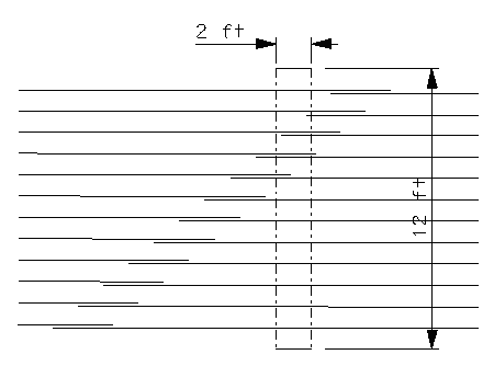
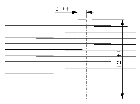
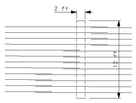
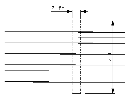
If all the splices occur at the same longitudinal location, transverse cracks that occur at the location could cause steel bonding failure, resulting in wide cracks and performance problems. To make sure that all the splices do not occur at the same transverse location, Item 360 requires staggering splices to avoid having more than 1/3 of the splices within any given 2-ft. longitudinal length and 12-ft. width of pavement. Splicing longitudinal steel is not allowed within 10 ft. of construction transverse joints.
Following are drawings (see Figure 9-15, Figure 9-16, Figure 9-17, and Figure 9-18) that show acceptable and non-acceptable splice locations or patterns.
Figure 9-15. Acceptable splicing pattern- 33% (4 of the 12 bars) within the box are spliced.
Figure 9-16. Acceptable splicing pattern.
Figure 9-17. Acceptable splicing pattern.
Figure 9-18. Non-acceptable splicing pattern – 66% of bars in the box are being spliced.
5.2.4 Holding the Reinforcing Steel in Place
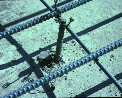
Contractors like to keep the steel mat from moving excessively prior to paving due to the paving operation itself or because of temperature changes. Figure 9-19 shows a piece of reinforcing steel being used as a pin. This pin can be left or removed before the concrete pour.
Figure 9-19. Pinning the mat.
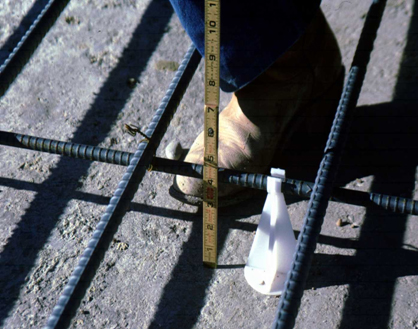
Reinforcing steel depth has an effect on CRCP performance. CRCP Design Standards require the tolerance of longitudinal steel at +/- 1 in. horizontally and +/- 0.5 in. vertically. Figure 9-20 illustrates the checking location of the steel.
Figure 9-20. Checking steel location.
