Section 7: Placement
Anchor: #i10299457.1 Introduction
In concert with the overall goal of operation synchronization, mix placement and compaction are the two most important elements in HMA pavement construction. Mix placement involves any equipment or procedures used to place the delivered HMA on the desired surface at the desired thickness. Mix placement can involve complicated asphalt paver operations or simple manual shoveling. This section provides a basic description of HMA placement operations. The Hot-Mix Asphalt Paving Handbook 2000 (TRB, 2001) and the Asphalt Institute's HMA Construction Manual (2001) contain detailed information on asphalt paver components.
Anchor: #i10300137.2 Placement Considerations
There are, of course, many considerations to take into account when placing HMA. Many are dependent upon local materials, weather, crew knowledge and training, and individual experience. This subsection presents a few of the basic considerations that apply in virtually all situations:
- Anchor: #YMPEWHAO
- Lift
thickness. A "lift" refers to a layer of pavement
as placed by the asphalt paver. In order to avoid mat tearing (which
generally shows up as a series of longitudinal streaks), a good
rule-of-thumb is that the depth of the compacted lift should be
at least three times the nominal maximum aggregate size (TRB, 2000).
Table 6-3 provides the minimum and maximum lift thickness for every
mix type.
Anchor: #i1054039Table 6-3: TxDOT Lift Thickness Requirements HMA Mixture Type
Nominal
Maximum
Aggregate Size
Minimum Lift
Thickness
(inches)
Maximum Lift
Thickness
(inches)
Typical Location of Pavement Layer
Dense Graded
(Items 340/341)
TY-A
1-1/2”
3.0”
6.0”
Base
TY-B
1”
2.5”
5.0”
Base/Intermediate
TY-C
3/4”
2.0”
4.0”
Intermediate/Surface
TY-D
1/2”
1.5”
3.0”
Surface/Level-Up
TY-F
3/8”
1.25”
2.5”
Surface/Level-Up
PFC
(Item 342)
PFC-F
or
PFCR-F
1/2”
0.75”
1.5”
Surface
PFC-C
or
PFCR-C
3/4”
1.0”
2.0”
Surface
Superpave Mixtures
(Item 344)
SP-A
1”
3.0”
5.0”
Base
SP-B
3/4”
2.25”
4.0”
Base/Intermediate
SP-C
1/2”
1.5”
3.0”
Intermediate/Surface
SP-D
3/8”
1.25”
2.0”
Surface/Level-Up
SMA
(Item 346)
SMA-C
3/4”
2.25”
4.0”
Intermediate/Surface
SMA-D
1/2”
1.5”
3.0”
Intermediate/Surface
SMA-F
3/8”
1.25”
2.5”
Surface
SMAR-C
3/4”
2.0”
4.0”
Intermediate/Surface
SMAR-F
3/8”
1.5”
3.0”
Surface
CAMa
(SS 3000)
CAM
3/8”
1.0”
2.0”
Base/Intermediate
Surfacea
Thin Overlay Mixtures
(Item 347)
TOM-C
TOM-F
1/2”
1/2”
0.75”
0.5”
1.25”
0.75”
Surface
Surface
Thin Bonded Friction Courses
(Item 348)
PFC-C
3/4”
1.0”
2.0”
Surface
PFC-F
1/2”
0.75”
1.5”
Surface
TY-A
3/8”
0.5”
0.75”
Surface
TY-B
1/2”
0.625”
1.0”
Surface
TY-C
3/4”
0.75”
1.25”
Surface
aGenerally not recommended as a surface mixture for pavements with a posted speed limit > 45 mph.
Anchor: #DWWNEKJT - Longitudinal joints. The interface between two adjacent and parallel HMA mats. Improperly constructed longitudinal joints can cause premature deterioration of multilane HMA pavements in the form of cracking and raveling, and potentially serve as a conduit for moisture damage to lower layers. Anchor: #LYFTHXWI
- Handwork. HMA
can be placed by hand in situations where the paver cannot place
it adequately. This can often occur around utilities, around intersection
corners, and in other tight spaces. Hand-placing should be minimized
because it is prone to aggregate segregation and results in a slightly
rough surface texture. If hand placement is necessary, the following
precautions should be taken (Asphalt Institute, 2001):
- Anchor: #NEPMMDJU
- Place the HMA in a pile far enough away from the placement area that the whole pile must be moved. If the pile is located in the placement area, its appearance, density, or aggregate distribution may be slightly different than the surrounding handworked mat. Anchor: #HYDTPQCW
- Carefully deposit the material with shovels and then spread with lutes. Do not broadcast (scoop and pitch) the HMA with shovels – this is likely to cause aggregate segregation. Anchor: #GGODRTTF
- All material should be thoroughly loosened and evenly distributed. Chunks of HMA that do not easily break apart should be removed and discarded. Anchor: #QPTRORPO
- Check the handworked surface with a straightedge or template before rolling to ensure uniformity.
Anchor: #ULUFTUYO - Stone Matrix Asphalt (SMA).
Gap-graded mixes behave differently than dense-graded mixes during
placement and compaction. Experience and understanding of dense-graded
mix placement should be augmented with specific training and precautions
before attempting to place an SMA for the first time. SMAs are generally
stickier and more difficult to work with than dense-graded mixes
because (1) they have more asphalt binder, (2) the asphalt binder
is modified, and (3) the binder and filler combination creates viscous
mastic. Also, it is not uncommon for large amounts of mastic (the
combination of asphalt binder and mineral filler) to collect on paving
equipment. If not carefully monitored, this mastic will release
from the equipment into the mat, leaving an over-asphalted area
– commonly referred to as a "fat spot." These considerations only
scratch the surface of SMA construction. A more thorough treatment
can be found in:
National Asphalt Pavement Association (NAPA) 2002. Designing and Constructing SMA Mixtures – State-of-the-Practice, Quality Improvement Series 122. National Asphalt Pavement Association. Lanham, MD.
Anchor: #VXDKQKYI - Thin Overlay Mixes (TOM); Thin Bonded Friction Courses. These mixtures are particularly vulnerable to rapid cool-down once placed and must be compacted promptly. Compaction cessation temperature (no further densification possible) is typically reached in less than 10 minutes, even under optimal conditions. WMA additives/processes may be effective in prolonging the compaction window by a few minutes when paving at lower ambient and surface temperature conditions. Using two breakdown rollers in tandem may expedite compaction when the compaction window is limited. Anchor: #MHJMIWRV
- Permeable Friction Course (PFC). Similar concerns of rapid cooling in compacting permeable friction courses exist as for the thin surface mixtures cited above. In addition, the compactive effort imparted should be the minimum necessary to seat the mixture without causing excessive breakage of the aggregate. A steel-wheeled roller, operated in the static mode, should be used. Mat problems. The asphalt paver, MTV, rollers, mix design, and manufacturing introduce many variables into flexible pavement construction. A familiarity with common causes of the more typical mat problems can help improve construction quality. Some common mat problems are micro cracking (checking), fat spots, joint problems, non-uniform texture (including mechanical segregation), roller marks, shoving, surface waves, tearing (streaks), and transverse screed marks. Compaction can also be compromised when working with certain mixtures that are prone to a “tender zone” phenomenon where the mat will encounter excessive lateral displacement and shoving when subject to roller loads. Any number of parameters can contribute to mixture tenderness, including excessive mix temperature, rounded aggregates, excessive binder content, and excessive moisture. Overcoming this tenderness state may be as simple as waiting several minutes for the mixture to cool slightly, or as problematic as developing a new mixture design.
7.3 Asphalt Paver
In 1934, Barber-Greene introduced the Model 79 asphalt laydown machine, a self-propelled formless laydown machine with a floating screed (Tunnicliff, Beaty and Holt, 1974). Since then, the basic concept of the asphalt paver has remained relatively unchanged:
- Anchor: #PUIYOVHU
- HMA is loaded in the front, Anchor: #NUIAIKFW
- carried to the rear by a set of flight feeders (conveyor belts), Anchor: #BRMROQJY
- spread out by a set of augers, Anchor: #BCCVWEHH
- then leveled and compacted by a screed.
This set of functions can be divided into two main systems:
- Anchor: #WABYTEDM
- the tractor (or material feed system), Anchor: #OHMFBMQY
- the screed.
7.3.1 Tractor (Material Feed System)
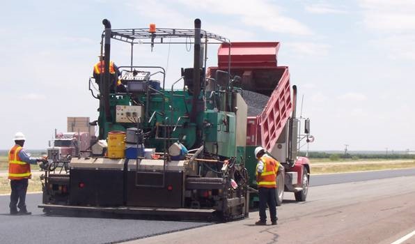
The tractor contains the material feed system, which accepts the HMA at the front of the paver, moves it to the rear, and spreads it out to the desired width in preparation for screed leveling and compaction. The basic tractor components are:
- Anchor: #KMHGMUNB
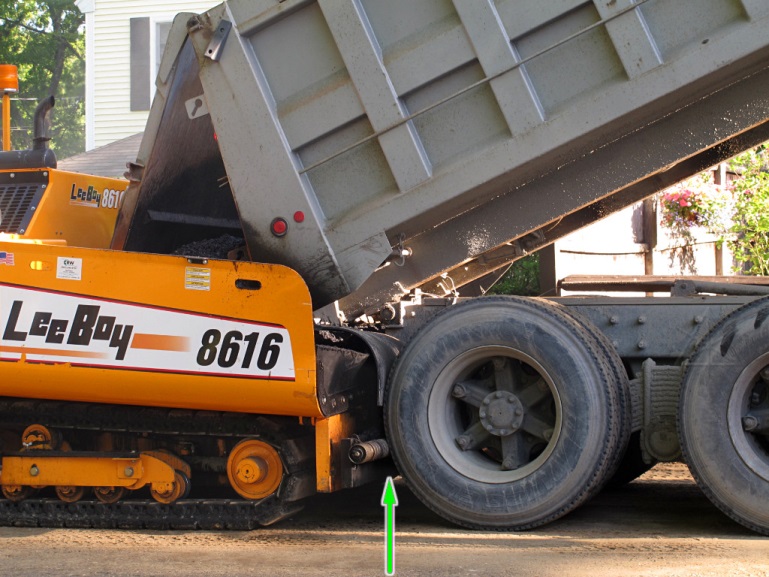
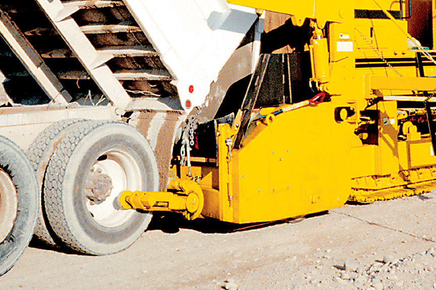
- Push
Roller and Truck Hitch. The push roller is the portion
of the paver that contacts the transport vehicle, and the truck
hitch holds the transport vehicle in contact with the paver (see Figure 6-23
and Figure 6-24). They are located on the front of the hopper.
Figure 6-23. Push Roller. © Copyright 2006 University of Washington
Figure 6-24. Truck hitch engaged. © Copyright 2006 University of Washington
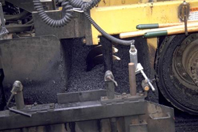
Anchor: #RWGWQPAV - Hopper. The
hopper is used as a temporary storage area for HMA delivered by
the transport vehicle. Therefore, the paver can accept more material
than is immediately needed and can use the volume in the hopper
to compensate for fluctuating material demands created by such things
as paving over irregular grades, utility access openings, or irregular
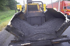
intersection shapes. Hopper sides (or “wings”) can be tilted up
(or “folded”) to force material to the middle where it is carried
to the rear by the conveyor system (see Figure 6-25). Hoppers can
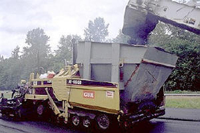
also be fit with inserts to allow them to carry more HMA (see Figure 6-26).
These inserts are typically used in conjunction with a material
transfer vehicle (MTV).
Figure 6-25. Hopper with wings folded up. © Copyright 2006 University of Washington
Figure 6-26. Caterpillar AP-1055B with hopper insert. © Copyright 2006 University of Washington
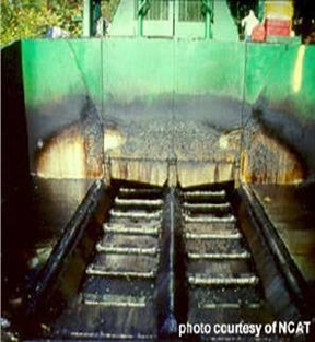
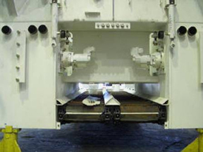
Anchor: #WHGUYTCD - Conveyor. The
conveyor mechanism carries the HMA from the hopper, under the chassis
and engine, and then to the augers (see Figure 6-27 and Figure 6-28).
The amount of HMA carried back by the conveyors is regulated by
either variable speed conveyors and augers or flow gates, which
can be raised or lowered by the operator or, more often, by an automatic
feed control system.
Figure 6-27. Conveyors. © Copyright 2006 University of Washington
Figure 6-28. Conveyors (seen from the rear of a partially built paver). © Copyright 2006 University of Washington
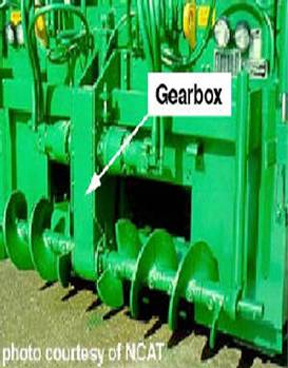
Anchor: #KBQFHHUA - Auger. The
auger receives HMA from the conveyor and spreads it out evenly over
the width to be paved (see Figure 6-29). There is one auger for
each side of the paver, and they can be operated independently.
Some pavers allow the augers to be operated in reverse direction
so that one can be operated forward and the other in reverse to
send all the received HMA to one side of the paver. The auger gearbox
can either be located in the middle (between the augers as shown
in Figure 6-30) or on the outside edge of each auger. If an inadequate
amount of HMA is distributed under a middle-located gearbox, the
result can be a thin longitudinal strip of mat aligned with the
gearbox that exhibits lower densities from aggregate segregation
and/or temperature differentials (see Figure 6-31 and Figure 6-32).
Figure 6-29. Augers distributing HMA. © Copyright 2006 University of Washington
Figure 6-30. Paver Augers (note, gearbox in between augers). © Copyright 2006 University of Washington
Figure 6-31. Gearbox Streak. © Copyright 2006 University of Washington
Figure 6-32. Gearbox streak in a new mat. © Copyright 2006 University of Washington
Operation of the tractor, and specifically the material feed system, can have significant effects on overall construction quality and thus long-term pavement performance. Although there are many detailed operational concerns, the two broad statements below encompass most of the detailed concerns:
- Anchor: #UALBOTPP
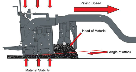
- HMA must be delivered to maintain a relatively constant head of material in front of the screed. This involves maintaining a minimum amount of HMA in the hopper, regulating HMA feed rate by controlling conveyor/auger speed and flow gate openings (if present), and maintaining a constant paving speed. As the next section will discuss, a fluctuating HMA head in front of the screed will affect the screed angle of attack and produce bumps and waves in the finished mat. Anchor: #LAUORYJS
- The hopper should never be allowed to empty during paving. This results in the leftover cold, large aggregate in the hopper sliding onto the conveyor in a concentrated mass and then being placed on the mat without mixing with any hot or fine aggregate. This can produce aggregate segregation or temperature differentials, which will cause isolated low mat densities. If there are no transport vehicles immediately available to refill the hopper, it is better to stop the paving machine than to continue operating and empty the hopper (TRB, 2000).
7.3.2 Screed
The most critical feature of the paver is the self-leveling screed unit, which determines the profile of the HMA being placed (Roberts et al., 1996). The screed takes the head of HMA from the material delivery system, strikes it off at the correct thickness, and provides initial mat compaction. This section describes screed terminology, basic forces acting on the screed, screed factors affecting mat thickness and smoothness, automatic screed control, and screed operation summary.
7.3.2.1 Screed Terminology
The following is a list of basic screed components and terms:
- Anchor: #YMFEYFEC
- Screed plate. The flat bottom portion of the screed assembly that flattens and compresses the HMA. Anchor: #RNDTDLEK
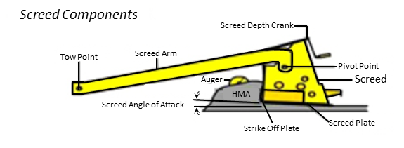
- Screed angle (angle of attack). The angle the screed makes with the ground surface (see Figure 6-33). Anchor: #OHCHRYQO
- Strike-off plate. The vertical plate just above the leading edge of the screed used to strike off excess HMA and protect the screed’s leading edge from excessive wear. Anchor: #MBXFDUGE
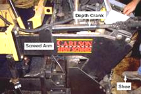
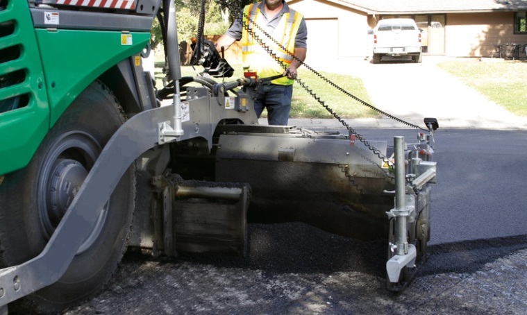
- Screed arms. Long beams that attach the screed to the tractor unit (see Figure 6-34). Anchor: #QUJWVGVM
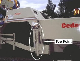
- Tow point. Point at which the screed arm is attached to the tractor unit (see Figure 6-35). Anchor: #MMYNISYO
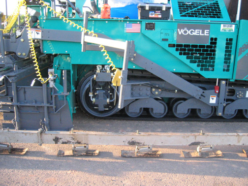
- Depth crank. The manual control device used to set screed angle and, ultimately, mat thickness. Anchor: #FVKBJRPG
- Screed heater. Heaters used to preheat the screed to HMA temperature. HMA may stick to a cold screed and cause mat tearing. After the screed has been in contact with the HMA for a short while (usually about 10 min.), its temperature can be maintained by the HMA passing beneath it and the heater can be turned off. If the screed is removed from contact with HMA for an extended period of time, it may need to be preheated again before resuming paving. Anchor: #UOQHTCOC
- Screed vibrator. Device located within the screed used to increase the screed’s compactive effort. Screed compaction depends upon screed weight, vibration frequency, and vibration amplitude. Anchor: #HVLLFLEO
- Screed extensions.
Fixed or adjustable additions to the screed to make it longer (see
Figure 6-36 and Figure 6-37). Basic screed widths are between 2.4
m (8 ft.) and 3.0 m (10 ft.). However, often it is economical to
use wider screeds or adjustable width screeds. Therefore, several
manufacturers offer rigid extensions that can be attached to a basic
screed or hydraulically extendable screeds that can be adjusted
on the fly.
Figure 6-33. Screed angle of attack.
Figure 6-34. Screed close-up showing the screed arm and depth crank. © Copyright 2006 University of Washington
Figure 6-35. Tow Point. © Copyright 2006 University of Washington
Figure 6-36. Hydraulic Screed Extension. © Copyright 2006 University of Washington
(This screed is extended too far [resulting in poor mix delivery and placement] and the tack coat is subpar.)
Figure 6-37. Screed Extension. © Copyright 2006 University of Washington
7.3.2.2 Screed Forces
There are six basic forces (see Figure 6-38) acting on the screed that determine its position and angle (Roberts et al., 1996):
-
Anchor: #FCGKGVNF
- Towing force. This is provided by the tractor and exerted at the tow point. Thus, towing force is controlled by paver speed. Anchor: #VNJBHDXU
- Force from the HMA head resisting the towing force. This is provided by the HMA in front of the screed and is controlled by the material feed rate and HMA characteristics. Anchor: #IWGGDSHR
- Weight of the screed acting vertically downward. This is obviously controlled by screed weight. Anchor: #IDGIQRCL
- Resistive upward vertical force from the material being compacted under the screed. This is also a function of HMA characteristics and screed weight. Anchor: #TAHQLGUH
- Additional downward force applied by the screed’s tamping bars or vibrators. This is controlled by vibratory amplitude and frequency or tamping bar force. Anchor: #PVMTIRQU
- Frictional force between the screed and the HMA under the screed. This is controlled by HMA and screed characteristics.
Figure 6-38. Screed Components and Forces. © Copyright 2006 University of Washington
7.3.2.3 Factors Affecting Mat Thickness and Smoothness
- Anchor: #BMKDMQJX
- Since the screed is free floating, it will slide across the HMA at an angle and height that will place these six forces in equilibrium. When any one of these forces is changed, the screed angle and elevation will change (which will change the mat thickness) to bring these forces back into equilibrium. Therefore, changing anything on the paver that affects these forces (such as paver speed, material feed rate, or screed tow point) will affect mat thickness. Furthermore, since mat thickness needs to be closely controlled, pavers have controls to manually set screed angle rather than rely on a natural equilibrium to determine mat thickness. Anchor: #PJMKPNRX
- In typical paving operations, the screed
angle is adjusted to control mat thickness. In order to understand
how a manually controlled screed angle affects mat thickness, a
brief discussion of how the paver parameters of speed, material
feed rate, and tow point elevation affect screed angle, screed height,
and, therefore, mat thickness is provided.
-
Anchor: #AGAIHKOP
- Speed. Paver speed affects mat thickness by changing the screed angle. If a paver speeds up and all other forces on the screed remain constant, the screed angle decreases to restore equilibrium, which decreases mat thickness. Similarly, as paver speed decreases, screed angle increases, which increases mat thickness. Anchor: #TXYIFOJX
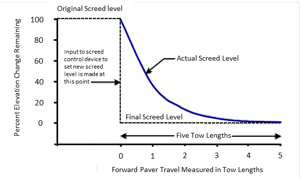
- Material Feed Rate. The amount of asphalt mixture in front of the screed (the material “head”) can also affect screed angle and thus mat thickness. If the material head increases (either due to an increase in material feed rate or a reduction in paver speed), screed angle will increase to restore equilibrium, which increases mat thickness. Similarly, if the material head decreases (either due to a decrease in material feed rate or an increase in paver speed), screed angle will decrease to restore equilibrium, which decreases mat thickness (TRB, 2000). Therefore, in order to maintain a constant mat thickness for a change in paver speed or material head in front of the screed, the natural equilibrium of forces on the screed cannot be relied upon, and the screed angle must be manually adjusted using a thickness control screw or depth crank. Screed angle adjustments do not immediately change mat thickness, but rather require a finite amount of time and tow distance to take effect. Figure 6-39 shows that it typically takes five tow lengths (the length between the tow point and the screed) after a desired level is input for a screed to arrive at the new level. Because of this screed reaction time, a screed operator who constantly adjusts screed level to produce a desired mat thickness will actually produce an excessively wavy, unsmooth pavement.
Figure 6-39. Screed reaction to a manual decrease in screed angle, (after TRB, 2000). © 2006 University of Washington
- Anchor: #SDHUOMDH
- Tow Point Elevation. Finally, tow point elevation will affect screed angle and thus mat thickness. As a rule-of-thumb, a 25 mm (1 in.) movement in tow point elevation translates to about a 3 mm (0.125 in.) movement in the screed's leading edge. Without automatic screed control, tow point elevation will change as tractor elevation changes. Tractor elevation typically changes due to roughness in the surface over which it drives. As the tow point rises in elevation, the screed angle increases, resulting in a thicker mat. Similarly, as the tow point lowers in elevation, the screed angle decreases, resulting in a thinner mat. Locating the screed tow point near the middle of the tractor significantly reduces the transmission of small elevation changes in the front and rear of the tractor to the screed. Moreover, because the screed elevation responds slowly to changes in screed angle, the paver naturally places a thinner mat over high points in the existing surface and a thicker mat over low points in the existing surface (TRB, 2000). The interaction of paver speed, material feed rate, and tow point elevation determine the screed position without the need for direct manual input. This is why screeds are sometimes referred to as "floating" screeds.
7.3.2.4 Automatic Screed Control
As discussed previously, the screed angle can be manipulated manually to control mat thickness. However, tow point elevation is not practical to manually control. Therefore, pavers usually operate using an automatic screed control, which controls tow point elevation using a reference other than the tractor body. Since these references assist in controlling HMA pavement grade, they are called “grade reference systems” and are listed below (Roberts et al., 1996):
-
Anchor: #FTNVEMHF
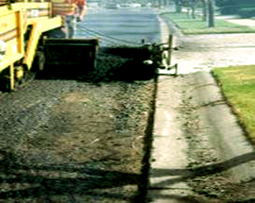
- Erected stringline. This consists of stringline erected to specified elevations that are independent of existing ground elevation. Most often this is done using a survey crew and a detailed elevation/grade plan. Although the stringline method provides the correct elevation (to within surveying and erecting tolerances), stringlines are fragile and easily broken, knocked over, or inadvertently misaligned. Lasers can be used to overcome the difficulties associated with stringlines because they do not require any fragile material near the pavement construction area. Lasers can establish multiple elevation or grade planes even in dusty or high-electronic and light-noise areas and are, therefore, sometimes used to construct near-constant elevation airport runways. The laser method becomes quite complicated, however, when frequent pavement grade changes are required. Anchor: #KJLOPFPX
- Mobile reference. This consists of a reference system that travels with the paver, such as a long beam or tube attached to the paver (called a "contact" device since it actually touches the road – see Figure 6-40) or an ultrasonic device (called a "non-contact" device since it relies on ultrasonic pulses and not physical contact to determine road elevation). The mobile reference system averages the effect of deviations in the existing pavement surface over a distance greater that the wheelbase of the tractor unit. Minimum ski length for a contact device is normally about 7.5 m (25 ft.) with a typical ski length being on the order of 12 to 18 m (40 to 60 ft.) (Asphalt Institute, 2001). Anchor: #YSPXDBKV
- Joint matching shoe.
This usually consists of a small shoe or ski attached to the paver that
slides on an existing surface (such as a curb) near the paver. Ultra
sonic sensors accomplish the same task without touching the existing
surface by using sound pulses to determine elevation. This type
of grade control results in the paver duplicating the reference
surface on which the shoe or ski is placed or ultra sonic sensor
is aimed.
Figure 6-40. Automatic grade control using a mobile reference beam. © Copyright 2006 University of Washington
In addition to grade control, the screed can also be set to control pavement slope and/or crown. A slope controller uses a slope sensor mounted on a transverse beam attached to the screed to determine screed slope, then adjusts screed slope to the desired amount. Generally, one side of the screed is set up to control grade and the opposite side is set up to control slope based on that grade. The usual practice is to run grade control on the side of the screed nearest the pavement centerline and run slope control on the screed side nearest the pavement edge because it is easier to match the centerline joint if grade control is used on that side of the paver (TRB, 2000).
Screed crown (the elevation of the middle in relation to the edges) can also be controlled. Typically, screeds offer separate front and rear crown controls. If crown control is used, the front control is usually set to a slightly more severe crown than the rear control to allow for easier passage of HMA under the screed.
7.3.2.5 Screed Operation Summary
The floating screeds used by today’s pavers are acted upon by six basic forces, which when left undisturbed result in an equilibrium screed angle and elevation that determines mat thickness. Adjusting paver speed, material feed rate, or tow point elevation will change these forces and result in a new equilibrium screed angle and elevation, and eventually a new mat thickness. In order to achieve the most consistent thickness and smoothest possible surface, pavers attempt to maintain a constant speed, use automatic feed controls to maintain a consistent head of material in front of the paver, and use automatic screed control to maintain a consistent tow point. Although the screed angle can be adjusted manually to change mat thickness, excessive adjustments will result in a wavy, unsmooth mat. In addition to grade, screeds can also control mat slope and crown to provide almost complete control over mat elevation at any location.
7.4 The Spray Paver
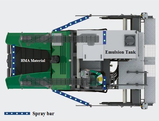
The spray paver is an asphalt paving machine that combines the processes of applying tack and paving a bituminous mixture into one machine. The tack emulsion may be applied in a heavy application, sometimes referred to as a membrane, that should be more effective in “sealing” the existing surface than would normally be expected of a tack. Spray nozzles are positioned either just in front of the augurs or in multiple locations on the paver to provide full coverage for the HMA mat placed immediately following the tack application. This process eliminates tracking of the applied tack by construction or other vehicles. Spray pavers can be used with thinner bonded wearing surfaces (Item 348) or conventional HMA applications. An example of a spray paver is shown in Fig. 6-41.
Figure 6-41. Spray Paving Machine (Courtesy of Wirtgen/Vögele).
Anchor: #i10491237.5 Thermal Profiling
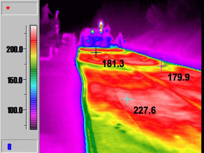
Thermal profiles are used to check the level and variability of the mixture temperature behind the paving machine. The applicable test procedure is Tex-244-F. Densification efforts will be impaired if the mixture has cooled below an appropriate compaction temperature (cessation temperature) for the mat thickness and mixture type. Additionally, if there is a lack of temperature uniformity in the mixture caused by thermal or mechanical segregation, excessive paving machine stop time, etc., compactive efforts will be encumbered. Thermal segregation is a known cause of compaction-related density problems that can lead to moisture infiltration and raveling of the mixture. A mat temperature differential behind the paving machine exceeding 25ºF but not exceeding 50ºF is classified as moderate thermal segregation. A mat temperature differential exceeding 50ºF is classified as severe thermal segregation.
7.5.1 Thermal Camera
Thermal Camera. A thermal camera records a still shot of the HMA mat temperature distribution directly behind the paving machine (and in front of the rollers). The camera must meet requirements in Tex-244-F and have the ability to display the view’s high and low temperature on an LCD screen. The contractor is required to conduct a thermal profile for each sublot placed over a test section measuring roughly 150 ft. behind the paver. Corrective action must be taken for recurring moderate thermal segregation, and operations must be suspended to eliminate severe thermal segregation (See Fig. 6-42). Areas detected with severe thermal segregation must be evaluated further using the segregation density profile procedure outlined in Tex 207-F.
Figure 6-42. Thermal Camera Image Showing Moderate Thermal Segregation.
7.5.2 Thermal Imaging System
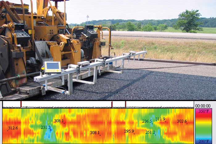
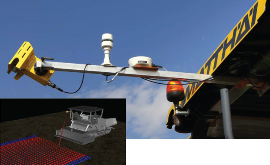
Thermal imaging systems are an innovative advancement in the monitoring of the uniformity of the mixture placement temperature behind the paver screed. The system was developed through TxDOT research and has since been commercialized with additional improvements. Figures 6-43 and 6-44 show an early version of the system and an innovative single scanning IR sensor head system that moves the apparatus away from the low mounting position on the catwalk just behind the screed. The ability to monitor the full-width mat temperature distribution in real-time allows the paving crew to make rapid adjustments to the paving operation that improve the uniformity of the placement temperature, if necessary. An electronic record is generated of the thermal profile tied to longitudinal offset using a distance measuring instrument (DMI) and global positioning system (GPS) coordinates. Electronic copies of the profiles are provided to the engineer; the engineer may suspend operations if the contractor cannot successfully modify the paving process to eliminate recurring severe thermal segregation. Test method Tex-244-F details the apparatus and procedural requirements needed to employ thermal profiling. HMA specifications (Items 341, 342, 344, 346, 347, and 348) offer contractor incentives to use this imaging technique by eliminating the contractor’s requirement to run density profiles (not applicable for Items 347, 348), and by relaxing the placement temperature requirements.
Figure 6-43. Early Version of the Thermal Imaging System.
Figure 6-44. Thermal Profiling Using a Single Scanning Sensor Head (Photo courtesy of MOBA).
Anchor: #i10499747.6 Material Transfer Vehicles (MTVs)
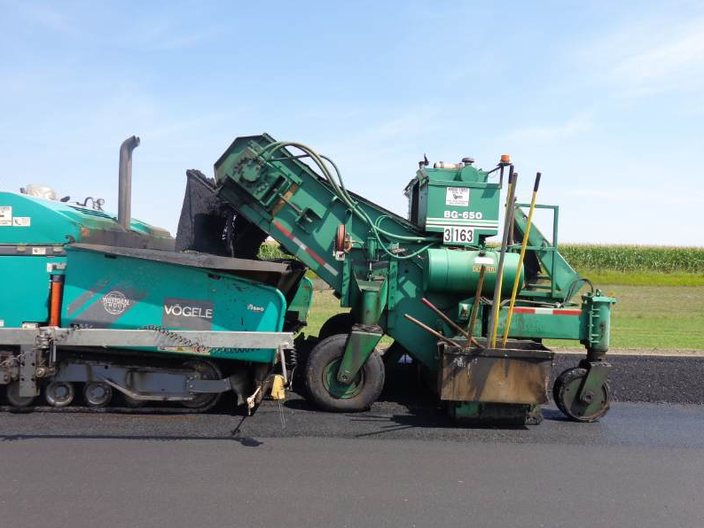
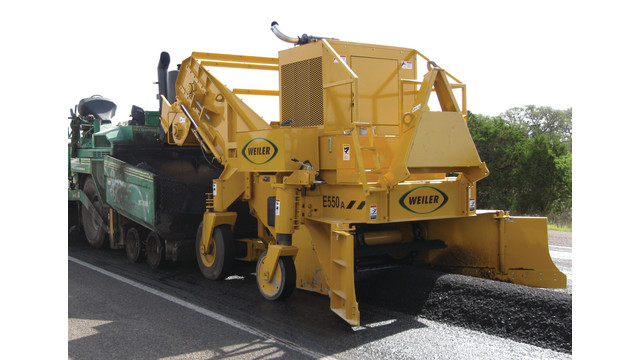
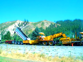
MTVs are used to assist the paver in placing HMA. Most pavers are equipped to receive HMA directly from end dump or live bottom trucks; however, in certain situations, it can be necessary or advantageous to use an MTV. Paving using bottom dump trucks and windrows requires a windrow elevator MTV (see Figure 6-45 and Figure 6-46), while other MTVs are used to provide additional surge volume, which is advantageous because it allows the paver to operate continuously without stopping, minimizes truck waiting time at the paving site and may minimize aggregate segregation and temperature differentials. This subsection covers:
- Anchor: #MLMWIXQT
- Windrow elevators Anchor: #BTLHPXXY
- Surge volume and remixing MTVs.
7.6.1 Windrow Elevators
Windrow elevators are positioned directly in front of pavers and are designed to pick up HMA placed in a windrow and transfer it to the paver hopper. This allows for (1) windrows to be used and (2) virtually continuous paving without stopping. When using windrows and windrow elevators, the windrow laydown rate must match the paver laydown rate. If the amount of material in the windrow is too little or too much, the paver may become overloaded or may run dry and have to stop. To avoid this, windrow paving operations typically have some method (e.g., a loader) available to add or subtract material from the windrow. Some windrow paving operations establish a windrow laydown rate slightly less than the paver laydown rate then periodically add material to the windrow with an end dump truck. Other windrow paving operations leave periodic spaces in the windrow to avoid paver overloading.
Figure 6-45. Windrow paving. © Copyright 2006 University of Washington
Figure 6-46. Windrow Elevator. © Copyright 2006 University of Washington
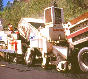
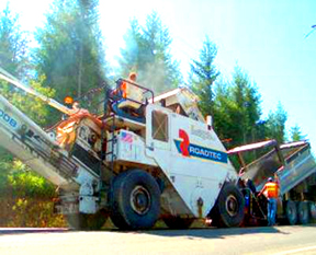
Other MTVs are used to provide an additional surge volume for the paver (see Figure 6-47, Figure 6-48 and Figure 6-49). This surge volume allows for continuous paver operations. With an MTV, the paver no longer has to stop while one truck leaves and the next truck backs up. Additionally, the MTV serves as a buffer between the paver and the haul trucks, which eliminates most truck bumping problems. Finally, most MTVs offer some sort of remixing capability that remixes the cool HMA crust formed during transport with the hot interior HMA to produce a more uniform mix entering the paver. This remixing can essentially eliminate aggregate segregation and temperature differentials. Some states have actually implemented specifications that require a remixing MTV for paving contracts where segregation and temperature differentials are of concern.
7.6.2 Surge Volume and Remixing MTVs
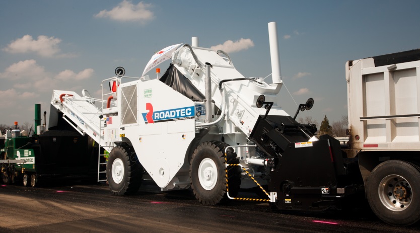
Surge volume/remixing MTVs are typically used in tandem with a paver hopper insert that increases the capacity of the paver hopper (see Figure 6-50). The insert is removable and sometimes contains remixing apparatus (such as a pugmill) near the bottom. At least one manufacturer has developed a paver solely for use with an MTV. The Roadtec StealthTM paver uses gravity feed and does not contain conveyors, hopper wings, or push rollers, which reduces initial cost as well as maintenance costs (Roadtec, 2001).
Figure 6-47. Blaw Knox MC-30 MTV. © Copyright 2006 University of Washington
Figure 6-48. Cedarapids MS-3 MTV. © Copyright 2006 University of Washington
Figure 6-49. Roadtec Shuttle Buggy MTV. © Copyright 2006 University of Washington
Figure 6-50. Roadtec Shuttle Buggy, front view, showing loading hopper for end dump and live bottom trucks. © Copyright 2006 University of Washington
Figure 6-51. Roadtec Shuttle Buggy Patented Remixing Auger. © Copyright 2006 University of Washington
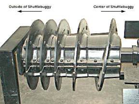
Remixing thoroughness varies from one type of MTV to the next. One idea that seems to work well is the Roadtec Shuttle Buggy patented remixing auger (see Figure 6-51). The auger employs three different pitches that get progressively bigger towards the center of the MTV. This allows for additional material to enter the auger area each time the pitch is increased, resulting in thorough remixing.
In summary, MTVs assist with the transfer of HMA from the transport trucks to the paver. There are two basic types of MTVs:
- Anchor: #WFRFGWFB
- windrow elevator MTVs, and Anchor: #QUKYXJQA
- surge volume/remix MTVs.
Windrow elevator MTVs are used to pick up HMA from a windrow and place it into the paver hopper, while surge volume/remix MTVs provide an additional material surge volume that allows for continuous paving and/or a remix capability that can reduce aggregate/temperature segregation. MTV use costs money and will increase the per ton cost of HMA paving but can help provide superior mat quality. However, MTVs should not be used as a substitute for good production and laydown practices, which are fundamental to good mat quality.
