Section 3: Hydraulic Grade Line Analysis
Anchor: #i1008165Introduction
Analyze the system’s hydraulic grade line (sometimes referred to as the HGL) to determine if you can accommodate design flows in the drainage system without causing flooding at some location or causing flows to exit the system at locations where this is unacceptable.
Anchor: #i1008175Hydraulic Grade Line Considerations
Develop the hydraulic grade line for the system to determine probable water levels that may occur during a storm event. You can then evaluate these water levels with respect to critical elevations within the designed facility. The development of the hydraulic grade line is a last step in the overall design of a storm drain system.
The hydraulic grade line is the locus of elevations to which the water would rise if open to atmospheric pressure (e.g., piezometer tubes) along a pipe run (see Figure 6-11). The difference in elevation of the water surfaces in successive tubes separated by a specific length usually represents the friction loss for that length of pipe, and the slope of the line between water surfaces is the friction slope.
If you place a pipe run on a calculated friction slope corresponding to a certain rate of discharge, a cross section, and a roughness coefficient, the surface of flow (hydraulic grade line) is parallel to the top of the conduit.
If there is reason to place the pipe run on a slope less than friction slope, then the hydraulic gradient would be steeper than the slope of the pipe run (pressure flow).
Depending on the elevation of the hydraulic grade line at the downstream end of the subject run, it is possible to have the hydraulic grade line rise above the top of the conduit. That is, the conduit is under pressure until, at some point upstream, the hydraulic grade line is again at or below the level of the soffit of the conduit.
")
Figure 6-11. Hydraulic Grade Line
Analyze to determine the flow characteristics of the outfall channel. Use the tailwater level occurring in the outfall to the storm drain system in the development of a hydraulic grade line.
Use a realistic tailwater elevation as the basis for the hydraulic grade line calculation. If the outfall tailwater is a function of a relatively large watershed area (such as a large stream) and you base the contribution from the storm drain system on a relatively small total watershed area, then it is not realistic to use a tailwater elevation based on the same frequency as the storm drain design frequency. Refer to Section 3 of Chapter 5 for the design frequency in the hydraulic grade line development of a storm drain system.
Anchor: #i1008228Stage versus Discharge Relation
Generally a stage versus discharge relation for the outfall channel is useful. Refer to the Slope Conveyance Procedure in Chapter 7 for considerations and a procedure leading to the development of a stage versus discharge relation in an outfall channel.
As a normal design practice, calculate the hydraulic grade line when the tailwater surface elevation at the outlet is greater than the soffit elevation of the outlet pipe or boxes. If you design the system as a non-pressure system, ignoring junction losses, the hydraulic grade line eventually will fall below the soffit of the pipe somewhere in the system, at which point the hydraulic grade line calculation is no longer necessary. Generally, check the hydraulic grade line. However, such calculations are not needed if the system has all of the following characteristics:
- Anchor: #DMFGVEAI
- All conduits are designed for non-pressure flow. Anchor: #BYPFBFOV
- Potential junction losses are insignificant. Anchor: #MUKLDDKY
- Tailwater is below the soffit of the outfall conduit.
If the proposed system drains into another enclosed system, analyze the downstream system to determine the effect of the hydraulic grade line.
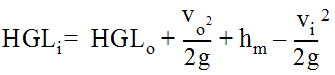
Anchor: #i1008265Conservation of Energy Calculation
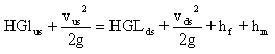
When defining the hydraulic grade line, calculations proceed from the system outfall upstream to each of the terminal nodes. For department practice, base calculation of the hydraulic grade line on conservation of energy as shown in Equation 6-22 which includes major and minor energy losses within the system. For conduit, d=1.
Equation 6-22.
where:
- Anchor: #NGRROHCW
- HGLus = 2 + d = elevation of the hydraulic grade line at upstream node (ft. or m) Anchor: #EDNNOLJT
- vus = upstream velocity (fps or m/s) Anchor: #JECWMCAL
- vds = downstream velocity (ft./s or m/s) Anchor: #GMUGDRQD
- hm = minor (junction/node) head loss (ft. or m) Anchor: #HEWLSUHJ
- hf = friction head loss (ft. or m) Anchor: #WQAJCFQW
- HGLds = elevation of hydraulic grade line at downstream node (ft. or m) Anchor: #PTTNWFHD
- g = 32.2 ft./ s2 or 9.81 m/s2.
Minor Energy Loss Attributions
Major losses result from friction within the pipe. Minor losses include those attributed to junctions, exits, bends in pipes, manholes, expansion and contraction, and appurtenances such as valves and meters.
Minor losses in a storm drain system are usually insignificant. In a large system, however, their combined effect may be significant. Methods are available to estimate these minor losses if they appear to be cumulatively important. You may minimize the hydraulic loss potential of storm drain system features such as junctions, bends, manholes, and confluences to some extent by careful design. For example, you can replace severe bends by gradual curves in the pipe run where right-of-way is sufficient and increased costs are manageable. Well designed manholes and inlets, where there are no sharp or sudden transitions or impediments to the flow, cause virtually no significant losses.
Anchor: #i1008339Entrance Control
Generally treat a storm drain conduit system as if it operates in subcritical flow. As such, entrance losses of flow into each conduit segment are mostly negligible. However, if discharge enters into the system through a conduit segment in which there must be supercritical flow, significant head losses are encountered as the discharge builds enough energy to enter the conduit. This situation is most likely where a lateral is located on a relatively steep slope. On such slopes, evaluate the type of flow (subcritical or supercritical).
With supercritical flow, the lateral may be operating under entrance control. When a lateral is operating under entrance control as described above, the headwater level is usually much higher than a projection of the hydraulic grade line.
If the entrance control headwater submerges the free fall necessary for the inlet to function properly, it may be necessary to reconfigure the lateral by increasing its size or changing its slope. Some improvement to the inlet characteristics may help to overcome any unfavorable effects of entrance control. Usually, entrance control does not affect steep units in the trunk lines because the water is already in the conduit; however, you may need to consider velocity head losses.
Use the following procedure to determine the entrance control head:
- Anchor: #BWKDJJFV
- Calculate critical depth as discussed in Critical Depth in Conduit earlier in this section. Anchor: #MIWQJXDJ
- If critical depth exceeds uniform depth, go to step 3; otherwise, no entrance control check is necessary. Anchor: #KMSMKLMD
- Calculate entrance head in accordance with the Headwater Under Inlet Control subsection in Chapter 8. Anchor: #JOMIWSMM
- Add entrance head to flowline and compare with the hydraulic grade line at the node. Anchor: #GAPVYBXV
- Take the highest of the two values from step 4. Check to ensure that this value is below the throat of the inlet.
Hydraulic Grade Line Procedure
Use the following procedure to determine the entrance control head:
- Anchor: #XYYICJAF
- Determine an appropriate water level in the outfall channel or facility. For an open channel outfall, the appropriate water level will be a function of the stage vs. discharge relation of flow in the outfall facility and designer’s selection of design frequency for the storm drain facility. If the outfall tailwater level is lower than critical depth at the exiting conduit of the system, use the elevation associated with critical depth at that point as a beginning water surface elevation for the Hydraulic Grade Line calculation. Anchor: #CJIGEQMV
- Compute the friction loss for each segment
of the conduit system, beginning with the most downstream run. The
friction loss (hf) for a segment of conduit
is defined by the product of the friction slope at full flow and
the length of the conduit as shown in Equation 6-23.
Equation 6-23.
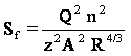
The friction slope, Sf, is calculated by rearranging Manning’s Equation to Equation 6-24.
Equation 6-24.
where:
- Anchor: #WNILBLET
- Sf = friction slope (ft./ft. or m/m) Anchor: #THPCJUAV
- Q = discharge (cfs or m3/s) Anchor: #POXJKGRI
- n = Manning’s roughness coefficient Anchor: #SXIFRJPW
- z = 1.486 for use with English measurements only. Anchor: #OANLTORX
- A = cross-sectional area of flow (sq. ft. or m2) Anchor: #AYPQOKOM
- R = hydraulic radius (ft. or m) = A / WP Anchor: #GJCCKSFJ
- WP = wetted perimeter of flow (the length of the channel boundary in direct contact with the water) (ft. or m).

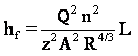
Combining Equation 6-23 with Equation 6-24 yields Equation 6-25 for friction loss.
Equation 6-25.
where:
- Anchor: #JWBKVINU
- z = 1.486 for use with English measurements units only. Anchor: #OKHMKFRN
- L = length of pipe (ft. or m).
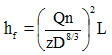
For a circular pipe flowing full, Equation 6-25 becomes Equation 6-26.
Equation 6-26.
where:
- Anchor: #NMUCMUDH
- z = 0.4644 for English measurement or 0.3116 for metric. Anchor: #YJTJAQJC
- D = Pipe diameter (ft. or m).
For partial flow, you could use Equation 6-25 to approximate the friction slope. However, the backwater methods, such as the (Standard) Step Backwater Method outlined in Chapter 7, provide better estimates of the hydraulic grade line.
- Anchor: #KNOQXPLE
- Using the downstream Hydraulic Grade Line elevation as a base, add the computed friction loss hf. This will be the tentative elevation of the Hydraulic Grade Line at the upstream end of the conduit segment. Anchor: #FOXPEVBM
- Compare the tentative elevation of the Hydraulic Grade Line as computed above to the elevation represented by uniform depth of flow added to the upstream flow line elevation of the subject conduit. Anchor: #VMXAPHWN
- The higher of the two elevations from step 2 above will be the controlling Hydraulic Grade Line elevation (HGLus) at the upstream node of the conduit run. (If you perform backwater calculations, the computed elevation at the upstream end becomes the Hydraulic Grade Line at that point). Anchor: #RDXYGKFS
- If other losses are significant, calculate
them using the procedures outlined below. Use Equation 6-27 to determine
the effect of the sum of minor losses (hm)
on the Hydraulic Grade Line.
Equation 6-27.
Anchor: #NYMXMAHF - If the upstream conduit is on a mild slope (i.e., critical depth is lower than uniform depth), set the starting Hydraulic Grade Line for the next conduit run (HGLds) to be the higher of critical depth and the Hydraulic Grade Line from step 3 (or 4 if minor losses were considered). Anchor: #SLHJUCQW
- Go back to step 2 and continue the computations in an upstream direction into all branches of the conduit system. The objective is to compare the level of the Hydraulic Grade Line to all critical elevations in the storm drain system. Anchor: #WKKFKFEN
- Check all laterals for possible entrance control head as described in the subsection below. Anchor: #DIAAHXHB
- If the Hydraulic Grade Line level exceeds a critical elevation, you must adjust the system so that a revised Hydraulic Grade Line level does not submerge the critical elevation (this condition is sometimes referred to as a “blowout.”) Most adjustments are made with the objective of increasing capacity of those conduit segments causing the most significant friction losses. If the developed Hydraulic Grade Line does not rise above the top of any manhole or above the gutter invert of any inlet, the conduit system is satisfactory.
NOTE: If the conduit system does not include any pressure flow segments but the outlet channel elevation is higher than the top of the conduit at the system exit, compute the Hydraulic Grade Line through the system until the Hydraulic Grade Line level is no higher than the soffit of the conduit. At this point, continuance of the Hydraulic Grade Line is unnecessary, unless other losses are likely to be significant.