Section 5: Storm Drain Inlets
Anchor: #i1015518Inlet Types
Inlets used for the drainage of highway surfaces into four major classes:
- Anchor: #VXPNAWSK
- Curb opening inlets - See Figure 10-2. Anchor: #RHMUTGPN
- Grate inlets - See Figure 10‑4. Anchor: #KPWOPUDO
- Linear drains - May be slotted drains ( Figure 10-5) or trench drains ( Figure 10-6). Anchor: #BPTIKJRF
- Combination inlets -- Combination inlets usually consist of some combination of a curb-opening inlet and a grate inlet. In a curb and grate combination, the curb opening may extend upstream of the grate.
Curb Opening Inlets
Figure 10‑2 illustrates a generic example of a typical curb opening inlet. Curb inlets are used in urban sections of roadway along the curb line.
Figure 10-5. Curb Opening Inlet
Most curb opening inlets depend heavily upon an adjacent depression in the gutter for effective flow interception (see Figure 10-3). Greater interception rates result in shorter (and probably, more economical) inlet lengths. However, a large gutter depression can be unsafe for traffic flow and bicycle operation near the gutter line. Therefore, a compromise is in order when selecting an appropriate value for the gutter depression. The depth of the gutter depression should be:
- Anchor: #OGDEAIRW
- 0 to 1 in. (0 to 25 mm) where the gutter is within the traffic lane Anchor: #YGLCRQEP
- 1 to 3 in. (25 to 75 mm) where the gutter is outside the traffic lane or in the parking lane Anchor: #NYBCPINR
- 1 to 5 in. (25 to 125 mm) for lightly traveled city streets that are not on a highway route.
Figure 10-6. Curb Opening Inlet Depression
Some municipalities in the state prefer to recess curb inlets with significant depression to minimize interference with traffic flow. The inlet is recessed from the line of the curb and gutter such that the depression does not extend beyond the gutter line. This may improve driveability; however, the curb transition may pose a hazard to traffic.
Curb opening inlets are useful in sag and on-grade situations because of their self-cleansing abilities and hydraulic efficiency. Additionally, they are often preferred over grate inlets because the inlet is placed outside the travel way and poses less of a risk to motorists and bicycle traffic.
A drawback of curb opening inlets is that the flowline of the opening is fixed and not readily adaptable to changing pavement levels as occur in surface treatment overlays. Successive overlays can gradually reduce or even eliminate the original opening available for water removal, unless the pavement edge is tapered to the original gutter line.
Anchor: #YBRJUDCJGrate Inlets
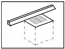
Figure 10-4 illustrates a typical grate inlet. Water falls into the inlet through a grate instead of an opening in the curb. Designers use many variations of this inlet type, and the format of the grate itself varies widely as each foundry may have its own series of standard fabrication molds.
Figure 10-7. Grate Inlet Schematic
For the most part, grate inlets are used in sag configurations in gutters, adjacent to concrete traffic barriers or rails (where curb inlets would not be practicable), V-shaped gutters with no curb or barrier, and ditches. Grate inlets may also be used at on-grade situations combined with curb inlets.
Grate inlets adapt to urban roadway features such as driveways, street intersections, and medians. When grate inlets are specified, the grate configuration and orientation should be compatible with bicycle and wheelchair safety.
Access to the storm drain system through a grate inlet is excellent in that, usually, the grate is removable. On the other hand, maintenance of grate inlets can be a continuing problem during the life of the facility; the propensity to collect debris makes grate inlets a constant object of maintenance attention. As such debris accumulates it obstructs the flow of surface water into the inlet. Grate inlets also present potential interference with bicycles and wheelchairs.
Anchor: #REIIILLFLinear Drains
Linear drains were designed for the interception of wide spread, low flow situations. Applications include intercepting sheet flow from the roadway when collection at a concentration point is not practical, or providing a generalized inlet for stagnate flow on pavements without slope. Linear drains have the advantage that no depression is necessary for hydraulic efficiency.
Linear drains may be useful in problematic areas where curb and grate inlets are ineffective, such as along a median barrier, and at super elevation transitions. Linear drains can also be installed transversely across the roadway.
However, linear drains have several drawbacks:
- Anchor: #VNGNKVOP
- Linear drains have a high propensity to collect debris in sag configurations. Regular maintenance is required to clear debris from over the drain inlet. Anchor: #ORTNQESH
- Installation can be difficult. Because the inlet is installed flush with the surface of the pavement, placement is critical.
Slotted Drains
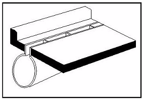
Slotted drains consist of a corrugated pipe with an extended slot, or throat, at the top (see Figure 10-5). The throat of a slotted drain inlet is ordinarily reinforced for structural integrity.
Figure 10-8. Slotted Drain Inlet
Slotted drains should be installed with sufficient slope to provide a cleaning velocity for the corrugations. If not, regular cleaning and maintenance must be scheduled on the slotted drain. Clean out access boxes are usually needed at the far end of each slotted drain run to facilitate regular maintenance and cleaning.
Anchor: #i1180801Trench Drains
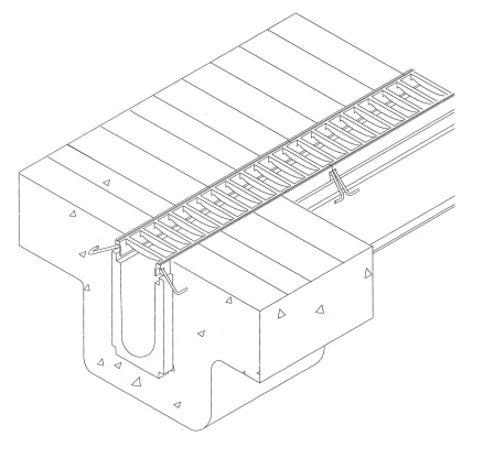
Trench drains may be precast or cast-in-place. Figure 10-6 illustrates the body and grate of an installed precast trench drain.
Figure 10-9. Precast trench drain.
Trench drains have the advantage of a shallower embedment depth and an extremely smooth invert that doesn’t retain sediments, but the disadvantage of having a limited volume because of their size.
Trench drains on Department roadways are required to have non-removable grates because removable grates may come loose or move which will create a traffic hazard. The grates specified by the Department have a minimum of 60% open space which allows for cleaning with a vacuum truck or water truck without removing the grates.
Anchor: #i1015765Combination Inlets
Combination inlets such as curb and grate can be useful in many configurations, especially sag locations. Because of the inherent debris problem in sags, the combination inlet offers an overflow drain if part of the inlet becomes completely or severely clogged by debris. Maintenance of combination inlets is usually facilitated by the fact that the grate is removable, providing easy access to the inlet and associated storm drain system.
Combination inlets used on-grade generally are not cost-effective because of the relatively small additional hydraulic capacity afforded. Authentic data on such combinations are insufficient to establish accurate factors for determining the true capacity of a combination inlet.
For a combination curb and grate, assume that the capacity of the combination inlet comprises the sum of the capacity of the grate and the upstream curb opening length. Ignore the capacity of the curb opening that is adjacent to the grate opening.
Anchor: #i1015785Inlets in Sag Configurations
An inlet in a sag configuration is considered the “end of the line” because the water and its debris load have no other place to go. Because of this, failure of an inlet in a sag configuration often represents a threat to the successful operation of a storm drain system. Therefore, the hydraulic designer must consider some additional items such as complex ponded width and complex approach slopes.
In a sag configuration, the controlling ponded width can be from one of two origins. The inlet itself may cause a head that translates to a ponded width, and the flow in the curb and gutter from each direction subtends its own ponded width.
If the sag is in a vertical curve, the slope at the sag is zero, which would mean that there is no gutter capacity. In reality there is a three-dimensional flow pattern resulting from the drawdown effect of the inlet. As an approximation, one reasonable approach is to assume a longitudinal slope of one half of the tangent grade.
Because the water or its debris load can go no other place, an appropriate safety factor should be applied to the inlet size. For grate inlets in sags, the usual safety factor is approximately two; for curb inlets, the factor can be somewhat less. In application, the factor of safety for a grate inlet is applied as a safety reduction factor, or clogging factor. For example, a safety factor of 2 would result in a clogging factor of 50%, which assumes that half the grate is clogged by debris.
Where significant ponding can occur such as in an underpass and in a sag-vertical curve, good engineering practice is to place flanking inlets on each side of the sag location inlet to relieve some or most of the flow burden on the inlet in sag. Flanking inlets should be analyzed as inlets on-grade at some specified distance (usually 50 or 100 feet) away from the low point on the sag vertical curve.
Anchor: #i1015809Median/Ditch Drains
Drains or inlets appearing in ditches and medians are usually grate inlets and are also termed “drop inlets.” The operation of the inlet is enhanced by a concrete riprap collar that forms a type of bowl around the inlet.
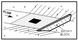
Often, such an inlet is in a sag (sump) configuration created by a ditch block. Department research ( 0-5823-1) indicates that a six inch ditch block may not be adequate to ensure complete capture of flow; a taller ditch block may be necessary. However, the designer must either determine the required depth for complete capture, or account for flow over the ditch block to the next inlet. Care must be taken to ensure that the ditch block slopes meet clear zone standards.
Figure 10-10. Median/Ditch Inlet
Anchor: #JXVONAUMDrainage Chutes
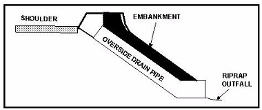
Drainage chutes, also referred to as over-side drains or curb slots, are commonly used at the ends of bridges to either prevent flow from running onto a bridge deck, or to prevent flow from running off a bridge deck onto the pavement. There may be other locations where a drainage chute or curb cut may be useful in removing flow from the pavement where no storm drainage system is present and where suitable outfall is present behind the curb and gutter section. In most cases, an opening in the curb connects to a scour-resistant channel or chute which prevents erosion of the embankment or slope. In some instances, the channel or chute may be replaced with a pipe placed in the roadway embankment as illustrated in Figure 10-8. This treatment facilitates mowing and other maintenance but also introduces its own maintenance needs to keep it from clogging.
Figure 10-11. Over-Side Drains
Anchor: #i1015846Inlet Locations
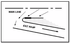
The inlet location may be dictated either by roadway elements, hydraulic requirements, or both. Inlets should be placed upstream of roadway elements such as sags, street intersections, gore islands (see Figure 10-9), super elevation transitions, driveways, cross-walks, and curb ramps (see Bypass Flow Design Approach). Flow across intersections, ramps, and to a lesser extent, driveways, may cause a traffic hazard, while flow across cross-walks and curb ramps may cause a pedestrian hazard. Inlets at these locations should be designed to capture 100% of the flow. Inlets should also be located hydraulically to prevent excessive gutter flow and excessive ponding.
Figure 10-12. Inlet at a Gore Island


