Chapter 10: Storm Drains
Anchor: #i1014036Section 1: Introduction
Anchor: #i1014041Overview of Urban Drainage Design
The objective of urban storm drainage is to optimize safe passage of vehicle traffic by collecting stormwater from the roadway, and to convey it safely to an adequate receiving body without undue risk to pedestrian traffic or contributing to damage of adjacent private properties during the design storm event.
The flow of water along a roadway can interfere with or halt highway traffic. The most destructive effects of an inadequate drainage system are damage to surrounding or adjacent properties, deterioration of the roadway components, and hazard or delay to traffic caused by excessive ponding in sags or excessive flow along roadway grades.
Proper drainage of a roadway in an urban region can be more difficult than draining roadways in sparsely settled rural areas for the following reasons:
- Anchor: #URCLQECD
- heavy traffic and subsequent higher risks Anchor: #RHVQSUWB
- wide roadway sections Anchor: #VNTMRYKT
- relatively flat grades, both in longitudinal and transverse directions Anchor: #DLWIXOQL
- shallow water courses Anchor: #DSWTMHMJ
- absence of side ditches and a presence of concentrated flow Anchor: #XQEDQKPR
- the potential for costly property damages that may occur from ponding of water or from flow of water through built-up areas Anchor: #NGPROXVF
- a roadway section that must carry traffic and act as a channel to carry the water to some disposal point.
These conditions require sound and consistent engineering principles and the use of all available data to achieve an acceptable drainage design.
Anchor: #i1014097Overview of Storm Drain Design
Although the design of a storm drain system entails many conventional procedures, the design also requires engineering judgment. The proper design of any storm drainage system requires accumulation of basic data, familiarity with the project site, and a basic understanding of the hydrologic and hydraulic principles and drainage policy associated with that design.
The development of a storm drain design requires a trial and error approach:
- Anchor: #PEUAGBSX
- Analyze a tentative storm drain system. Anchor: #EXJEGPQB
- Compare the system to design criteria. Anchor: #GITOBXMN
- Evaluate the system economically and physically. Anchor: #SHEQIPOI
- Revise the system if necessary. Anchor: #EFCGXLVU
- Analyze the revised system. Anchor: #YWUECXWM
- Make the design comparisons again. Anchor: #LPLLFRFY
- Repeat the process until a storm drain system has been developed that satisfies the technical function of collecting and disposing of the runoff within budgeted allowances.
The hydraulic designer must establish design parameters and criteria, decide component location and orientation, determine appropriate design tools, and ensure comprehensive documentation.
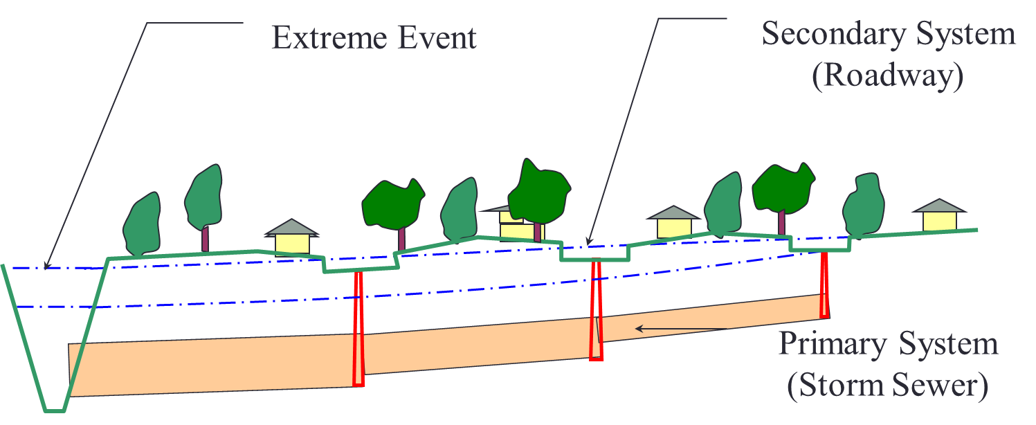
Of major importance in the design of urban storm drainage facilities is the realization that all storm drainage systems are comprised of two separate and distinct systems, namely the Primary System (storm sewer) and the Secondary System (roadway).
Figure 10-1. Drainage Systems (Storm Sewer and Roadway)
The primary system consists of a carefully designed storm drain with capacity to handle runoff for a relatively high frequency (e.g., 5–year event).
The secondary system is the conveyance of storm water when the primary system is inoperable or inadequate. This system usually accommodates flow exceeding the primary system’s design flow up to the 100–year event.
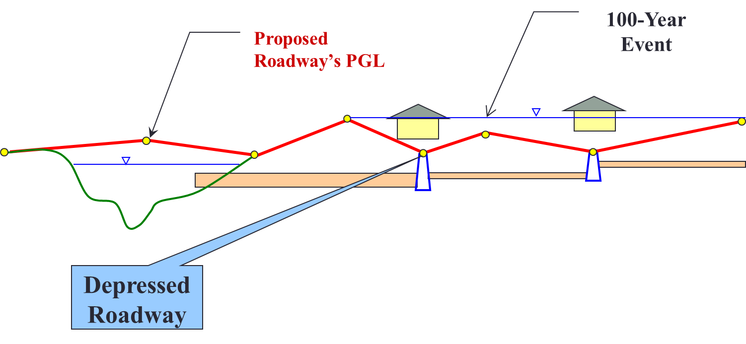
The lack of a properly designed secondary system often leads to flooding causing severe damage.
Figure 10-2. Improperly Designed Secondary System
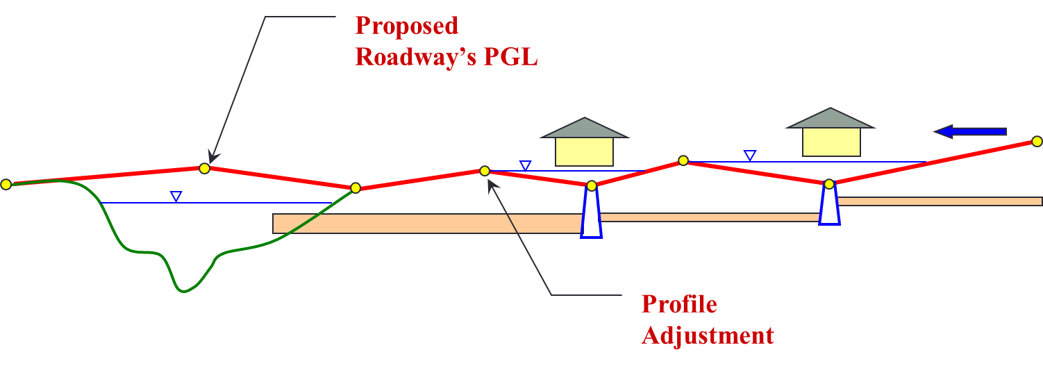
It is economically impractical to enlarge the primary system to avoid the need for the secondary system; but by careful attention to the roadway profile during the initial project planning stage, a secondary system can usually be incorporated at no significant cost.
Figure 10-3. Properly Designed Secondary System
For this reason a sheet flow analysis is recommended for every storm drain project. A sheet flow map is an overall map showing all high points, grade breaks, cul-de-sac bulbs and sub-drainage area divides. This map should also include top of curb elevations at all high points. Flow direction arrows must be included. With this map, the designer should consider where the storm runoff would go as ponding levels increase, how deep the water can get at one inlet location before it starts to spill downhill toward the next ponded area, and ultimately, how the sheet flow is going to reach its outlet. With this tool the designer can make adjustments to the roadway’s profile and terrain to accommodate the extreme flow event.


