Section 4: Pump Station Hydraulic Design Procedure
Anchor: #i1063975Introduction
The hydraulic design of a pump stations has two major components, the storage design and the pump selection.
Anchor: #i1013447Storage Design Guidelines
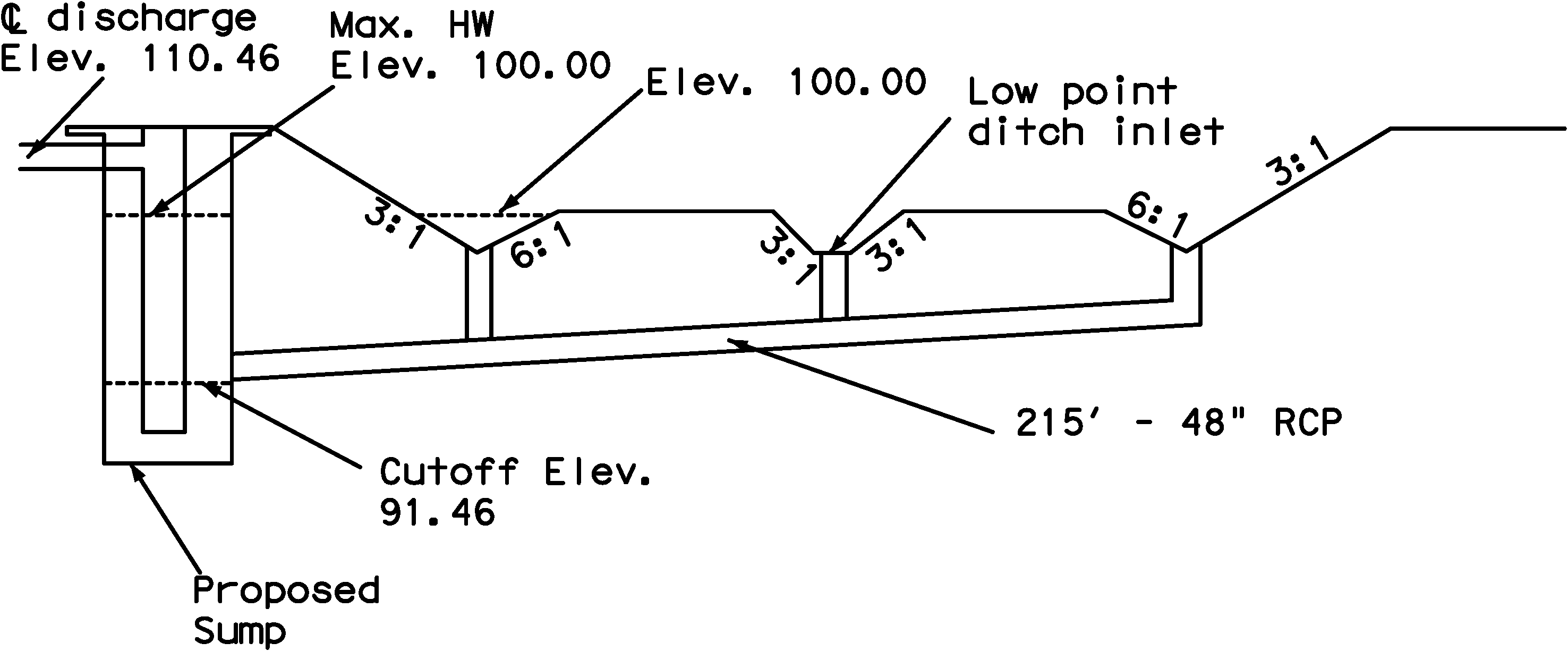
The storage volume of the wet well should be less than the total volume of the wet well because allowances should be made for a sump and for freeboard. The sump is the volume of the wet well below the required minimum water level, which is the pump cutoff elevation. The wet well must maintain water above the pump inlet to keep the pump from attempting to pump dry or sucking air. The sump must also have room below the pump intake level for sedimentation and heavy trash that wash into the system.
The top of the storage volume determines the maximum water level, the level in the wet well above which the water should not be allowed to exceed. Any freeboard above the maximum water level is not included in the calculated storage volume. Pumping is initiated at or below the maximum water level, and is stopped when the water drops to the minimum water level.
Other spaces outside of the wet well which can store storm water before flooding occurs may also be considered part of the available storage volume. These include sumps, pipes, boxes, inlets, manholes, and ditches of the storm drain system. The storm drain system can represent a significant storage capacity.
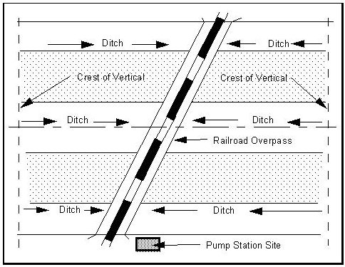
Figures 11-2 and 11-3 are a pump station location plan and cross section. The cross section shows how the storm system can provide additional storage outside of the wet well.
Figure 11-2. Pump Station Schematic
Figure 11-3. Typical Cross Section
Anchor: #i1064222Pump Selection
The selected rate of discharge from the pump station determines the number and size of pumps required for the facility. However, pump selection is a matter of economic analysis by the designer. To continue the example above using an allowable discharge of 100 cfs, Table 11-2 lists imaginary pumps data. For a real design, the designer must consult manufacturer's technical data to select a pump or combination of pumps to achieve the allowable discharge.
|
Pump Designation |
Pump Capacity |
|---|---|
|
Type AA |
5,000 gpm = 11.1 cfs |
|
Type BB |
6,000 gpm = 13.4 cfs |
|
Type CC |
7,000 gpm = 15.6 cfs |
|
Type DD |
8,000 gpm = 17.8 cfs |
|
Type EE |
9,000 gpm = 20.0 cfs |
|
Type FF |
10,000 gpm = 22.3 cfs |
From Table 11-2, five Type EE pumps (20 cfs x 5) will match the allowable pump rate of 100 cfs. Alternatively, four type FF pumps (22.3 cfs x 4) will yield a pump rate of 89.2 cfs, which is less than the allowable but still a significant discharge. However, the lower pump rate will require a larger wet well volume.
The designer must also consider the cost of construction and physical restrictions for the wet well. Enlarging the wet well and using fewer pumps might be a reasonable alternative to a larger wet well. In situations where one pump may be able to supply the entire discharge necessary, a minimum of two smaller pumps is recommended for reliability and maintenance. Multiple pumps also offer the opportunity for a staggered startup of pumps. Manufacturer's printed technical data and a sales or technical representative can be invaluable sources at this stage of the design in selecting the right pumps. The final design and pump selection must be based on all the considerations together.

