Section 2: ADABAS Feature Characteristics
Anchor: #i1021352Column Headers
Each of the defined data feature characteristics serve as column headers for data in the ADABAS matrix.
Anchor: #i1021362Feature Names
Feature Names is the ADABAS term for a TRM feature. The system uses this name to search for and retrieve the correct data records for ad hoc reporting purposes.
EXAMPLE: CI-CURVE-TYPE-CODE
The Common Name is a term used in input instructions and more likely heard in everyday conversation than the ADABAS name.
EXAMPLE: ‘Curve Type’ is easier to say than ‘CI-CURVE-TYPE-CODE’.
Anchor: #i1021376Data Classes
Three classes of data attributes/features in TRM are Key Data, Point Data, and Length Data:
- Key Data—Attributes/features
used to search, process, and store records in the data file:
Anchor: #i1015486Key Data Data
Description
Highway
- Signed Highway System
- Number
- Suffix, if any
From
- Reference Marker Number and Suffix closest to the beginning of the update
- Reference Marker Sign as positive if the direction to the beginning of the update is past the marker, or as negative if the direction to the beginning of the update is prior to the marker
- Reference Marker Displacement as the distance from the marker to the beginning of the update
To
- Reference Marker Number and Suffix closest to the ending of the update
- Reference Marker Sign as positive if the direction to the ending of the update is past the marker, or as negative if the direction to the ending of the update is prior to the marker
- Reference Marker Displacement as the distance from the marker to the ending of the update
Roadbed-Id
C, N, K, R, L, P, T, S, M, X, Y, A, B
- Point Data—A single location on the
roadway at which the given data feature resides:
Anchor: #i1015505Point Data Data
Description
Features such as Boundary Data, Maintenance Data, Marker Coordinates
- Use one reference marker number plus displacement
-
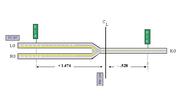
EXAMPLE: Record the intersection of two routes by setting a value to the reference marker plus displacement where the centerline of each route meets. In Figure 2‑1 below, Reference Marker 914 + a displacement of 1.474 (or Reference Marker 916 - a displacement of 0.528) is the location of the US 287/FM 1288 intersection.
-
Figure 2-1. FM 1288 intersects US 287 at Reference Marker 914 + 1.474 or Reference Marker 916 – 0.528.
- Length Data—The continuous value of a given feature from
a beginning point to an ending point on the roadway. Input the
value using two reference marker location points: the from Reference
Marker plus displacement (beginning of the value) and the to Reference
Marker plus displacement (ending of the value). The two types of
length data are:
Anchor: #i1015515Length Data Data
Description
Continuous
Values may change throughout an entire route, but there are no breaks or holes where no values exist.
EXAMPLE: Values for features like Speed Limit Maximum begin and end consecutively throughout the entire route with no holes (see Figure 2‑2 below).
Non-continuous
Values are not required to run consecutively throughout the route. Breaks or holes may exist.
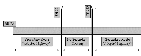
EXAMPLE: A secondary route can stop and start several times throughout the entire route (see Figure 2‑3 below).
-
Figure 2-2. Speed limit 65 ends where 55 begins; then 55 ends where 65 begins again.
-
Figure 2-3. First Secondary Route ends at SH 82; no Secondary route between SH 82 and SP 215, then another Secondary Route begins at SP 215.
Field Size
Field Size is the number of characters or digits allowed in the feature. Those with a decimal indicate both the number of digits before the decimal and the number of digits after the decimal.
EXAMPLE: Reference Marker Displacement consists of two digits before the decimal and three digits after the decimal. The field size is ‘2.3’.
Anchor: #i1021445Roadbed Classes
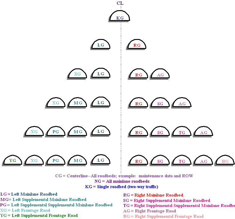
Locate most data in TRM not only by Signed Highway + Reference Marker location, but also by Roadbed-Identification (see Figure 2‑4).
Figure 2-4. Diagram of all TRM Roadbed-IDS.
Depending on an attribute’s roadbed classification, the system stores the value of a given feature either on all roadbeds of the route or only on some of the roadbeds. Attributes/ features have five general roadbed classes:
|
Class |
Descriptions and Examples |
|---|---|
|
Roadbed-Specific (RB) |
EXAMPLE: Speed Limit Maximum; within a given Reference Marker range, the system records the speed limit for each individual roadbed, even if the speed limit value is the same for all roadbeds. |
|
Centerline (CL) |
EXAMPLE: Secondary Route Designation; a given Reference Marker range includes all roadbeds with the one designation. |
|
Combination mainlanes plus individual frontage roads (MF) |
EXAMPLE: Administrative System—in a given Reference Marker range, all mainlane roadbeds have the same value, but values are recorded for each individual frontage road roadbed separately. |
|
Combination of the Left and Right Mainlanes (LR) |
EXAMPLE: Only Median Type and Width are this class; medians are recorded between the left and right mainlanes of a highway. |
|
Mixture (MX) |
EXAMPLE: Intersections—a highway intersects the left mainlane and not the right, or it crosses both the left and right, etc. The ARI diagram draws different symbols depending on whether the roadbed is N or a specific mainlane roadbed |
For more detail on inputting Roadbeds, go to Chapter 8 Roadbeds. .
Anchor: #i1021475Maintenance Responsibilities
Five areas of responsibility exist within TRM for maintaining and deleting data features:
|
Responsible Office |
Description |
|---|---|
|
Transportation Planning & Programming Division only (TPP) |
TPP has sole responsibility. |
|
District offices only (DIS) |
The specified district office has sole responsibility. |
|
District Office and TPP (TPP/DIS) |
The specified district office and TPP share responsibility. EXAMPLE: TPP is responsible for adding the first reference marker of a new route to TRM. From that point forward, the district office is responsible for that marker's maintenance. |
|
Construction Division only (CST) |
CST has sole responsibility. |
|
System Generated (SYS) |
The TRM system maintains these records. |


