Section 2: Reference Marker Installation Procedures
Anchor: #i1009316Installation
Each district installs new reference markers on the front and back of each reassurance route marker supporting post. Districts that want to install reference markers at additional locations, such as on each roadway or at closer intervals, need to contact TPP.
Use vehicles with calibrated distance measuring instruments (DMI's) or other more accurate distance measuring equipment. DO NOT USE standard vehicle odometers or trip meters; they are not as accurate. When using DMI equipped vehicles on a divided highway, take measurements while traveling on the inside lane in the direction of increasing mile posts. Reset the instrument to a known location at approximately every ten miles.
NOTE: The figures in this section are not to scale.
Anchor: #i1009338Location
Locate reference markers:
- On all routes, regardless of length
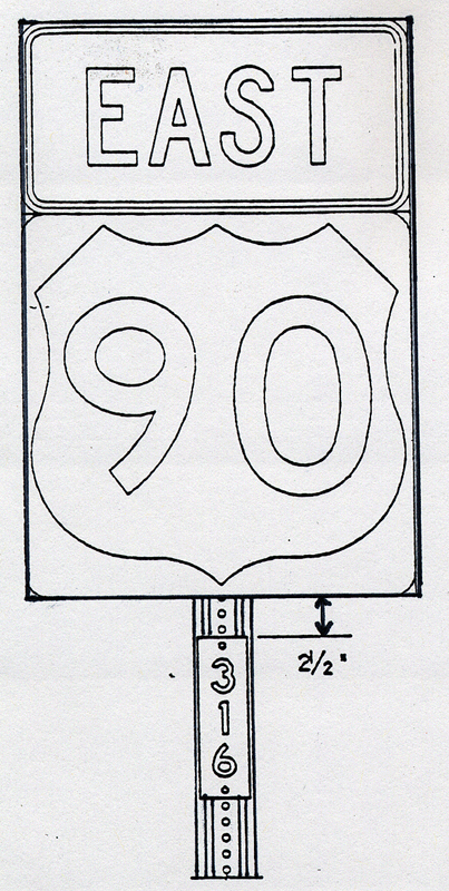
- On both sides of posts, two and one-half (2 ½) inches below the route marker so it is visible to drivers on both sides of the road.
Reference markers may be located:
- On frontage roads
- On roadbeds opposite the primary marker on divided highways (desirable)
- Approximately every two miles or less on alternating sides of single roadway highways.
Reference Marker Specifications
The districts should use:
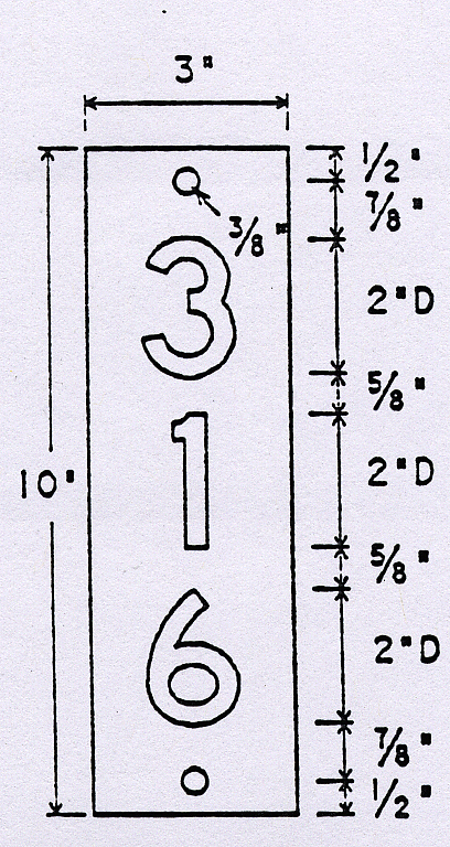
- 3” x 10” x 5/8" green reflective panels
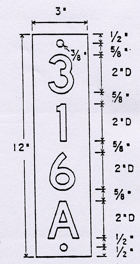
- 3” x 12” x 5/8” green reflective panels when reference marker number includes a suffix
- 2" tall numbers and letters that are series D, white engineer-grade, pressure-sensitive sheeting
- only capital letters.
Order the letters and numbers from the general warehouses by using the DHT numbers below:
|
DHT No. |
Number |
DHT No. |
Number |
DHT No. |
Letter |
|---|---|---|---|---|---|
|
3721 |
0 |
3736 |
5 |
121032 |
A |
|
3722 |
1 |
3727 |
6 |
121033 |
B |
|
3723 |
2 |
3728 |
7 |
121034 |
C |
|
3724 |
3 |
3729 |
8 |
- |
- |
|
3725 |
4 |
3730 |
9 |
- |
- |
NOTE: Letters D‑Z are available if needed.
This graphic shows how and where to place a reference marker on an existing sign:
Figure 7-3. Plaques to be mounted back to back.
This graphic shows how a reference marker should look on a pipe:
Figure 7-4. Plaque on pipe.
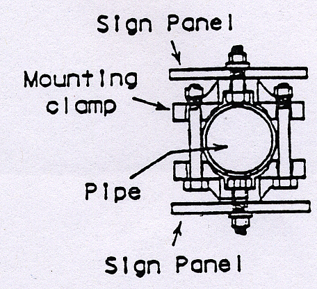
This graphic shows how to mount a reference marker on the pipe:
Figure 7-5. How to mount.
This graphic describes the sizes of the reference marker and numbers:
Figure 7-6. Reference marker without suffix.
This graphic describes the sizes of the reference marker, numbers, and suffix letters:
Figure 7-7. Reference marker with suffix.
This graphic shows how to handle low marker numbers by preceding the number with a zero so the reference marker number is three digits:
Figure 7-8. Example of low marker number preceded by a zero.
Use breakaway type mount design that leaves a stub in the ground, so you can accurately replace the mount.
This graphic shows how to set the reference marker pipe in relation to the highway in a business or residential area:
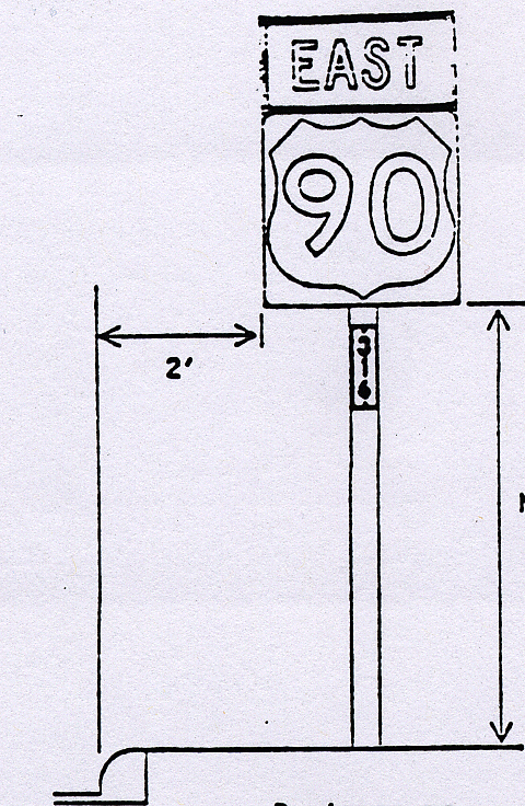
Figure 7-9. Business or residential area.
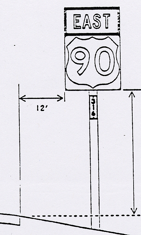
This graphic shows how to set the reference marker pipe in relation to the highway in a rural area:
Figure 7-10. Rural area.
Anchor: #i1009544Uniform Posting Procedures
Use these procedures to assign new reference marker numbers. Districts must include reference marker numbers on all PS&E package submissions. TPP assigns at least the beginning reference marker and notifies the districts.
TPP is responsible for coordinating procedures. The district reference marker coordinator shall notify TPP whenever a reference marker is moved, renumbered, removed, or added, or whenever questions need to be resolved.
NOTE: All signs posted must agree with the highway designation
Districts. District reference marker coordinators request assignment of reference marker numbers for all projects that:
- create a new route
- affect the reference marker's location on a current route (changes in the distance from route origin, route realignment etc.)
Include the following with the request:
- Approved schematics
- Any reference marker numbering sere previously agreed to by telephone with TPP
- Identification of all concurrent routes
- Disposition of an old section of a route (i.e., deletion, redesignation) with commission approval
Districts:
- Determine the number of markers needed and assign the subsequent number(s)
- Include the reference marker numbers and their locations in all plans, specifications and estimates packages
- Install the reference markers before opening either a new route or a realigned route to traffic
Notify TPP of the location of additional reference markers that the district needs or desires on an existing route:
EXAMPLE: Adding reference markers at closer intervals along a route, or to extended sections of routes. Accuracy will be at .01 mile from a known location like the primary marker.
Notify TPP of a change in the reference marker numbering scheme in the event that the district coordinator must reverse reference marker numbers on an existing route.
Do not move reference markers once they are physically in the ground unless absolutely necessary. In the event that you must move a reference marker, notify TPP of the new location. You must add a letter suffix to the reference marker number (see figure 7.2A for an exception).
NOTE: Post reference markers on temporary posts during roadway maintenance or construction work.
NOTE: If the district removes reference markers due to roadway work, accidents, or for any other reason, replace the markers in the same location as soon as possible.
Anchor: #i1009658Highway Hierarchy
The table at this link lists highways according to their hierarchy.
Anchor: #i1009670Developing a New Route in Sections
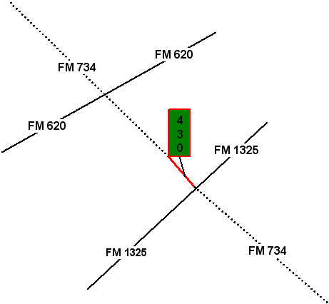
The first reference marker number is assigned by TPP:
Figure 7-11. Install RM 430 for the first section of FM 734.
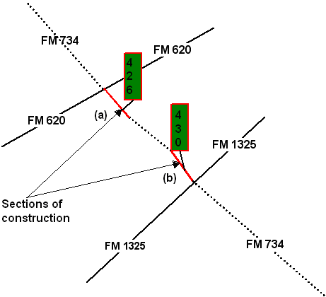
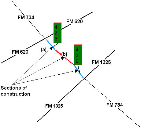
Additional sections of a route which are not contiguous with any other sections shall have a reference marker number assigned to them and these reference marker numbers shall be numbered based on their relationship to the existing reference marker numbers:
Figure 7-12. Sections a and b are not contiguous.
Additional sections of a route that are contiguous with other sections can use pre-existing reference marker numbers as their location keys:
Figure 7-13. Section b may use RM 426.
Anchor: #i1009720Joining Two Different Routes
Place new markers on the linking section of the joined route, approximately two miles from markers on the original routes. Number the new combined route or renumber a section in accordance with the overall route direction.
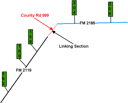
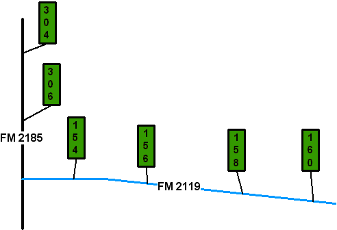
Example 1: If renumbering a section, the location of the markers stays the same, if possible, but the reference marker number changes. FM 2185 is a west-east route, 10 miles in length; FM 2119 is a north-south route, 50 miles in length:
Figure 7-14. Before renumbering.
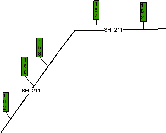
When joining the two routes, add a marker to the linking section and renumber the reference markers to reflect the new overall north-south direction:
Figure 7-15. After renumbering.
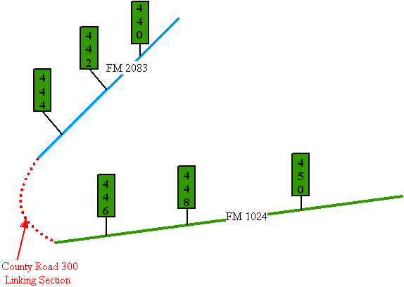
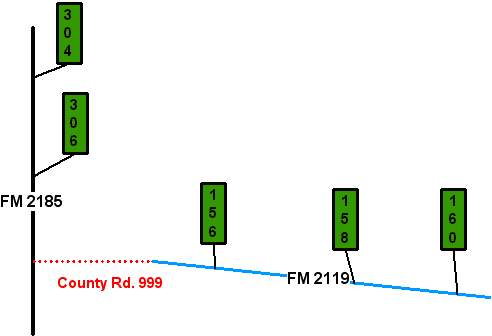
Example 2: The distance between existing markers is more than two miles, but the numbers are already in contiguous order:
Figure 7-16. FM’s are separated by a county road.
Choices for dealing with the linking section include:
- Adding an additional marker between existing markers OR
-
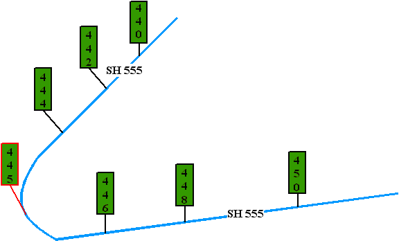
Figure 7-17. Add new RM 447 in the linking section.
- Moving existing reference markers closer together OR
-
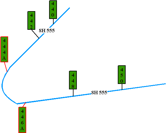
Figure 7-18. Physically move RM 446 and 448.
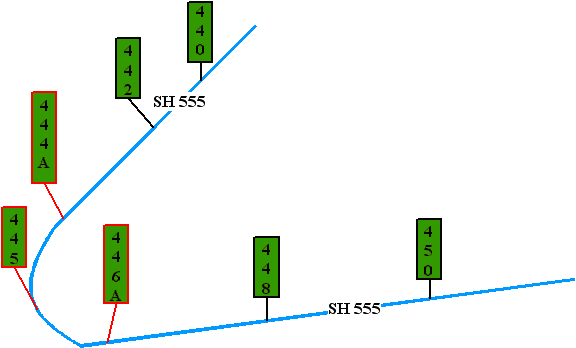
- Having existing reference markers closer together AND adding additional markers:
-
Figure 7-19. A combination of the two above.
Extending a Route
Add reference markers to the new section if needed or desired.
EXAMPLE: Add a reference marker if the distance between existing markers is greater than two miles between:
- The beginning of the route and the first marker
- The end of the route and the last marker:
-
Figure 7-20. FM 2119 extended from the beginning of the route.
-
Figure 7-21. New reference marker 154 added.
Realigning a Route
The realigned section has the same reference marker numbers, but will have a letter suffix added.
If necessary, markers on the realigned section can be spaced or added so that no renumbering is required.
The old section retains the same reference marker numbers and locations if possible
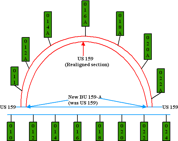
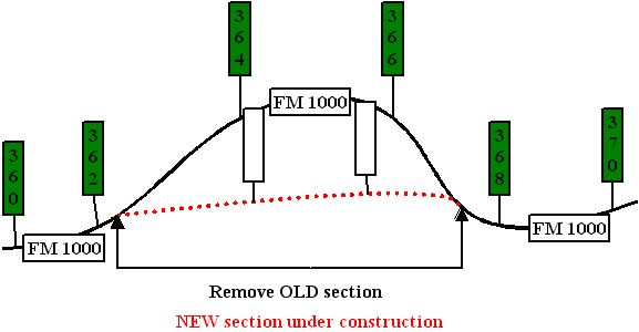
Example 1: When realigning a route and redesignating the old section, you may add reference markers but space the new reference markers so that you do not disturb the original numbering:
Figure 7-22. RM 011 added but not necessary.
Do not open routes at the same time with the same designation!
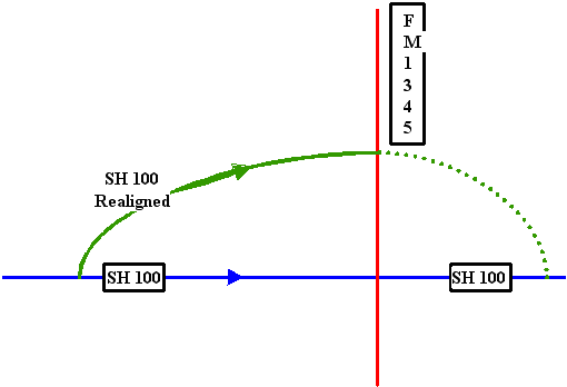
Example 2: Realigning a route. Figure 7‑23 shows the incorrect approach, leaving two routes open at the same time with the same designation:
Figure 7-23. There should never be a time when more than one route is open to traffic with the same designation and signing.
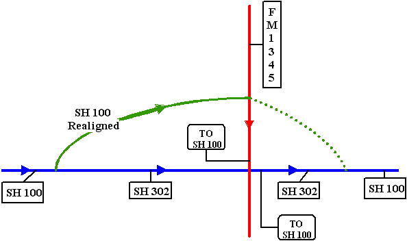
Figure 7‑24 is the correct approach showing the redesignation of the old section. SH 100 is temporarily trail blazed over FM 1345 and over SL 302, signed as “TO SH 100”:
Figure 7-24. Now, there is not more than one route open to traffic with the same designation and signing.
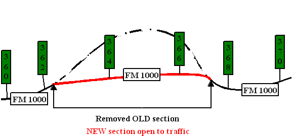
Example 3: No section is redesignated:
The construction plans indicate the locations of reference markers for the new route section:
Figure 7-25. The blank signs indicate where new reference markers may be placed.
If the old highway section is no longer under state maintenance, take it off the system and remove the reference marker posts:
Figure 7-26. The blank signs are assigned marker numbers.
Anchor: #i1009978Business Routes and Spurs
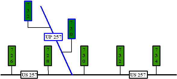
Select the initial reference marker in direct relation to the nearest reference marker number on the parent route.
NOTE: With the exception of interstate business routes, direction of travel and location on the grid map have no bearing on the initial assignment of reference marker numbers on spurs with parent routes or on business routes:
Figure 7-27. US Spur RM 730 directly relates to the nearest reference marker on US 257.
Anchor: #i1010003Circumferential Routes
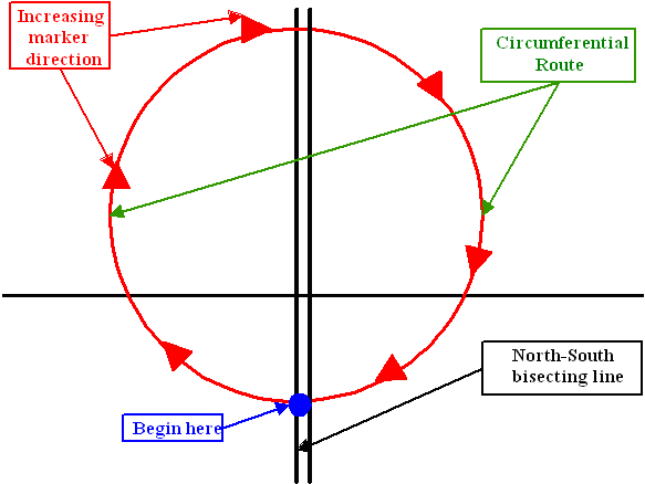
Number a circumferential (i.e. state highway loop) route in an east-to-west clockwise direction. The numbering begins with the first interchange west of an imaginary north-south line bisecting the circumferential route at an expressway, freeway, or interstate route, or some other conspicuous landmark in the circumferential route near a south “polar” location:
Figure 7-28. Begin at blue circle, move westward, northward, eastward, and southward back to blue circle.
Anchor: #i1010023Moving an Existing Reference Marker
If the new location affects the distance from route origin by more than 50 feet, add a letter suffix to the reference marker to show that the location has changed:
Figure 7-29. Add suffix to RM 222; RM 222 disappears.
If the new location affects the distance from route origin by less than 50 feet, do not add a letter suffix or update TRM.
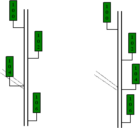
NOTE: Because TRM does not require alternating reference markers on either side of the roadway, Reference Marker Number 104 can simply be moved across the roadway:
Figure 7-30. Before and after.
Anchor: #i1010063Concurrent Routes
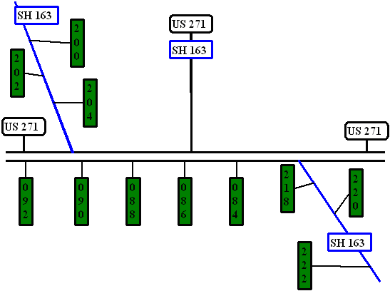
Reference marker numbers for the high order route take precedence:
Figure 7-31. US 271 takes precedence over SH 163.
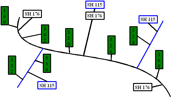
If the routes are the same order, the lower-numbered route takes precedence:
Figure 7-32. SH 115 takes precedence over SH 176.
